GOAL:
The goal for this project is to provide an adapter plate to mate a VQ35DE 6 speed transmission (CD) to an L-Series block. Our Z32 transmission adapters have worked well, but the hardest part for many folks is finding a machine shop capable of modifying the bellhousing at a reasonable cost. A key feature for this design was to come up with a solution that required little to no machining and can be done in the home garage.
I have owned a 350z track edition and now run a VQ35DE in my 240z, both of which used the CD transmission. The transmissions are wonderful to drive, they are very smooth and the shifting feel is direct. The later revision transmissions, CD009, have robust syncros and are capable of handling as much power as most L-Series builds can produce!
It is a close ratio transmission which gives a short first gear, great for low end acceleration in N/A when matched with a short rear, I run a 3.7 in my car. Turbo guys may want to opt for a 3.36 or 3.54 to help load the engine down low. All CD transmissions are interchangeable and can be had used for a reasonable price, especially earlier revisions, new transmissions are also available for under 1700 dollars.
Gear Ratios:
- 1st 3.794
- 2nd 2.324
- 3rd 1.624
- 4th 1.271
- 5th 1.000
- 6th 0.794
PROTOTYPE DESIGN:
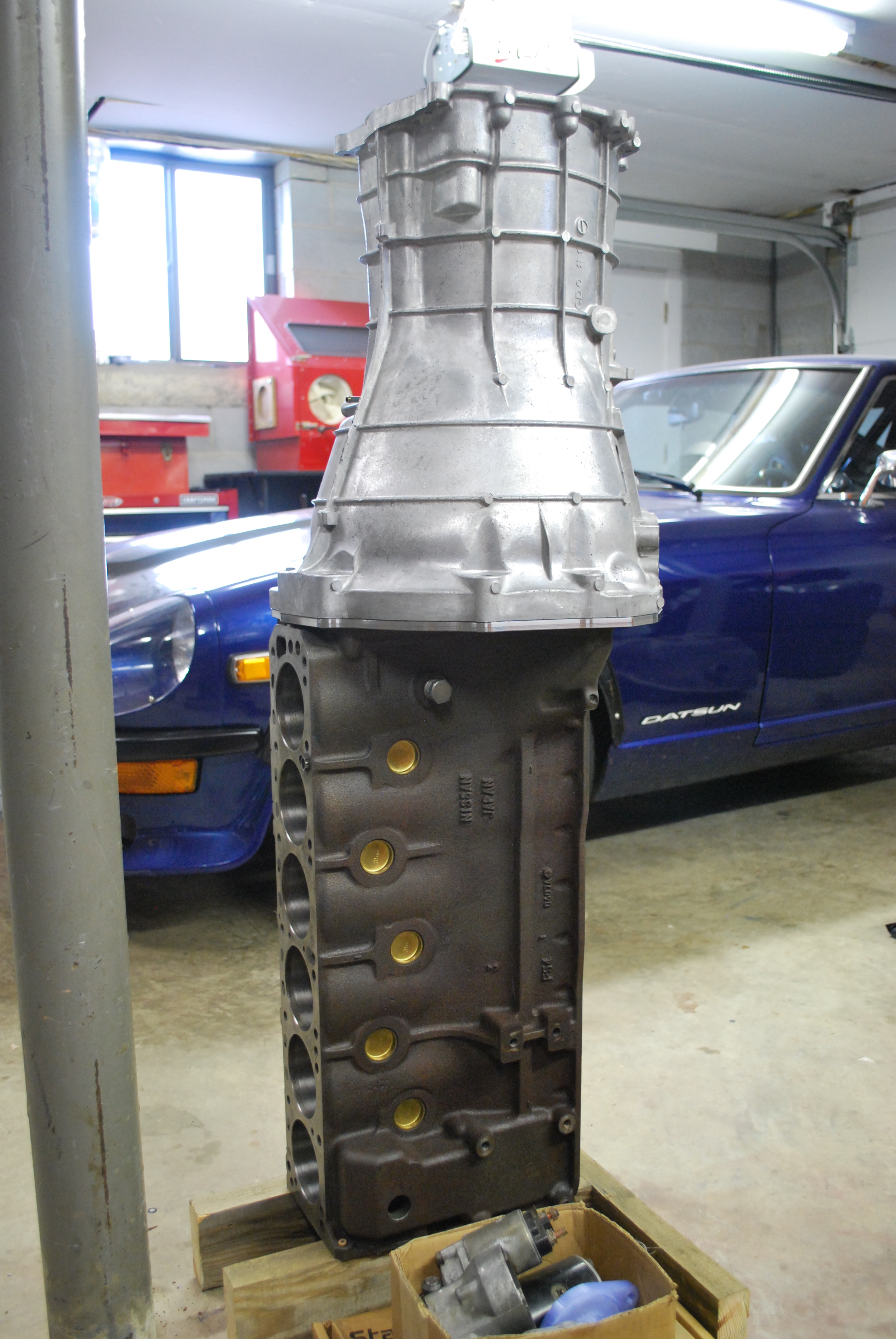
To kick off the project the 6spd bellhousing and block were delivered to a local machine shop with accurate measuring equipment. A CMM was used to capture the engine block mounting dimensions along with the crank centerline. The same was done with the transmission bellhousing except a vertical milling center was used for location which allowed us the reach to measure the input shaft bearing surface.
Profiles for the bellhousing and engine block were transferred by hand and scanned into the computer for digitization. The accurate bolt and alignment feature measurements along with the perimeter profiles provided the building block for the adapter plate design.


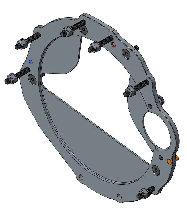
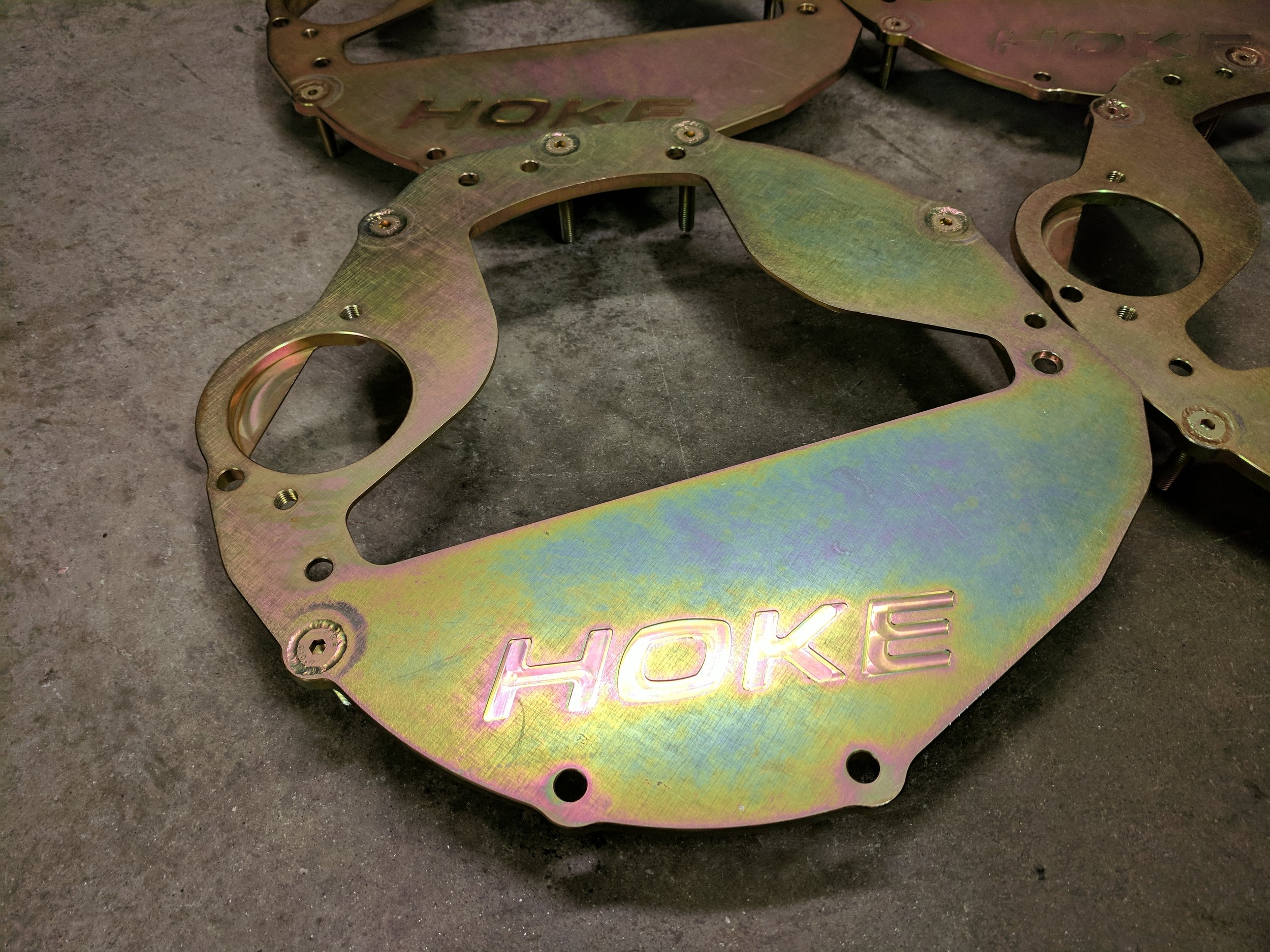
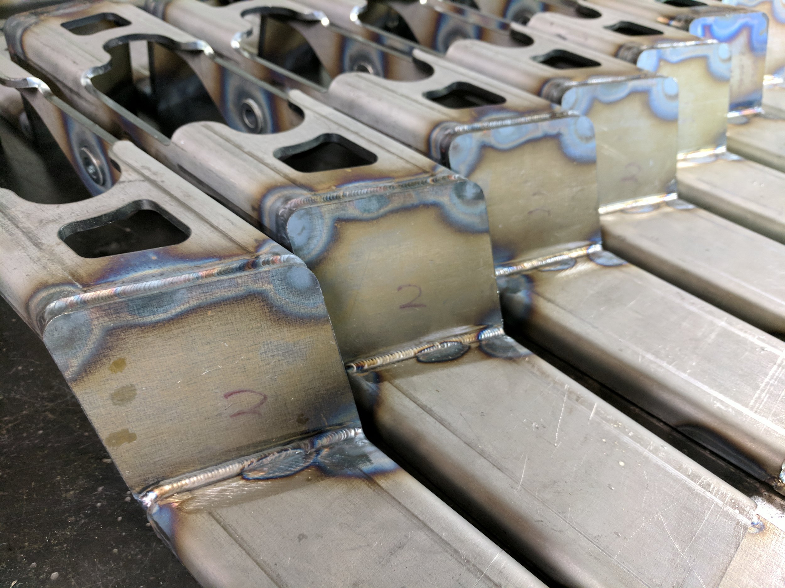
The first piece of the puzzle was to adapt the mounting patterns between the engine and transmission. Patterns were clocked in relation to one another to orient the transmission properly and maintain critical alignment features. A plate was designed from 3/8" steel which covers the entire perimeter of the bellhousing. This design makes for a stiff, thin plate, with minimal offset aiding in the no-machine design. The thin plate provides a challenge for thread engagment of the transmission mounting bolts, to overcome this FHCS where choosen as studs which are TIG welded to the plate.

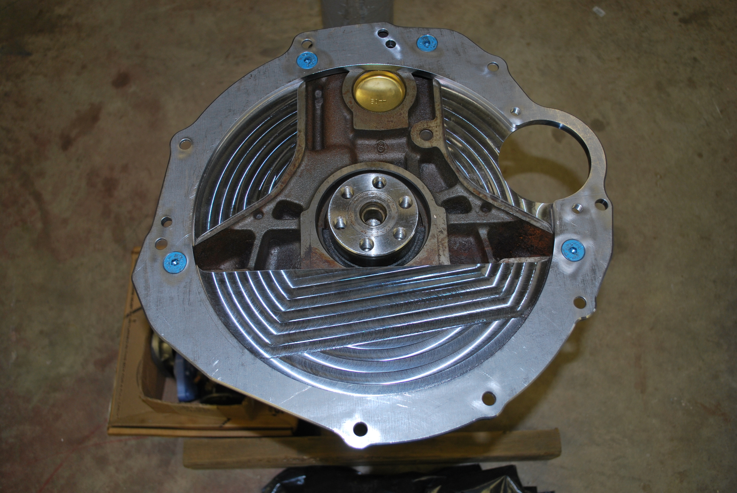
With the adpater plate design complete a few prototypes were made. The plate starts out as a laser cut blank which is then finish machined in a CNC mill. The final product turned out great with the engine and transmission aligning as intended.


The next challange was to properly align the L-Series clutch with the 6spd transmission input shaft and clutch hydraulics. The stock L-Series and 6Spd share the same input spline count. However the 350z's dual mass flywheel and clutch assembly is much taller then the L-Series which places the input shaft splines further away from the engine. The adapter also moves the transmission out a little further. These differences require the relocation of the L-Series clutch which can either be accomplished through a flwheel spacer, or a new custom flywheel.
The spacer route was initially explored as I percieved it to be a cheaper option that also allows for the use of any L-Series flywheel, as many people will have already upgraded this as part of their engine builds. Spacing the flywheel out not only requires a spacer, which must be precisly machined, but also requires custom flywheel bolts and stator relocation. Starter relocation was explored both by modifying a Tilton startor and by incorperating the offset into the adapter plate. Neither proved viable especially if machning of the bellhousing was to be elminated.
Ultimately it was decided a custom flywheel was the best route and would provide the most value for the kit. A stock flywheel and 3D printed spacers were used to ensure the new spacing was correct. The new flywheel maintained the same start ring gear location and center button dimensions. This allows for the L-Series starter to remain in the same location and for OE flywheel bolts to be used.
I had the flywheel machined by a custom drivetrain company and they turned out beautiful. These are balance and runout was checked on the protoypes to less then 0.001" on the friction surface. Looks can be a bit decieving as the flywheel is still 25% lighter then stock at 18.25lbs. 1 pc steel construction adds some piece of mind and allows for the use of either the 225 or 240mm clutch discs.
A new bronze pilot bearing was also designed to ensure full engagement on the input shaft.


As you can imagine the L-Series stater location does not line up with the reliefs on the 6spd bellhousing. However using a gear reduction starter from a 280zxt the issues is nearly eliminated since it does not have a nose over the spur gear. This starter requires only a small amount of material to be removed which can be done using a carbine bur on a die grinder. A 3D printed jig was designed to take the guess work out of the location and amount of material removal


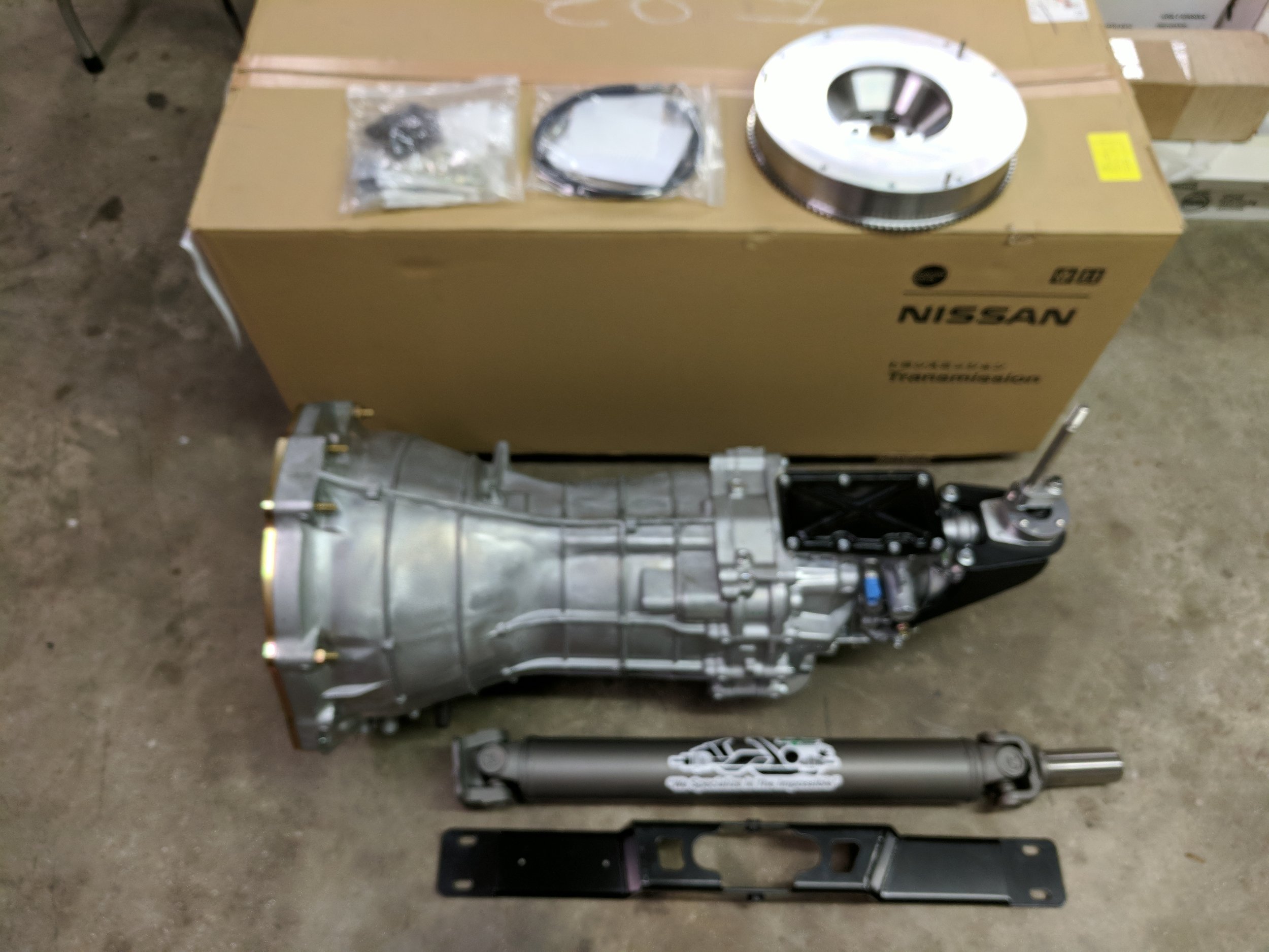
While we are working towards a complete bolt in solution I though it would be good to offer some 'DIY' kits for folks that were interesting in being an early adopter installing a kit in parallel with my vehicle developement. Included was everything needed to bolt the transmission to the engine, it was up to the installer to fabricate a transmission mount and either modify the console for a rearward shifter location or fabrication an alternative linkage! Here are a few pictures of those early kits!


A total of 5 DIY kits were made 4 were distributed to enthusist and the 5th was used for my in house installation. Of the 5 kits , 2 were sent out to 240z owners (1 beta tester and my shop installation), 2 to 280z owners, and 1 to a customer with a 280zx in Austrailia. The vehicle we are using for the shop installation is owned by Dan, a local enthusiast with a L28et equipped 240z. I was lucky to have him located so close and interested in being one of the first to test the 6 spd kit. I used this car to measure for the 240z transmission crossmember and develope the first prototypes.
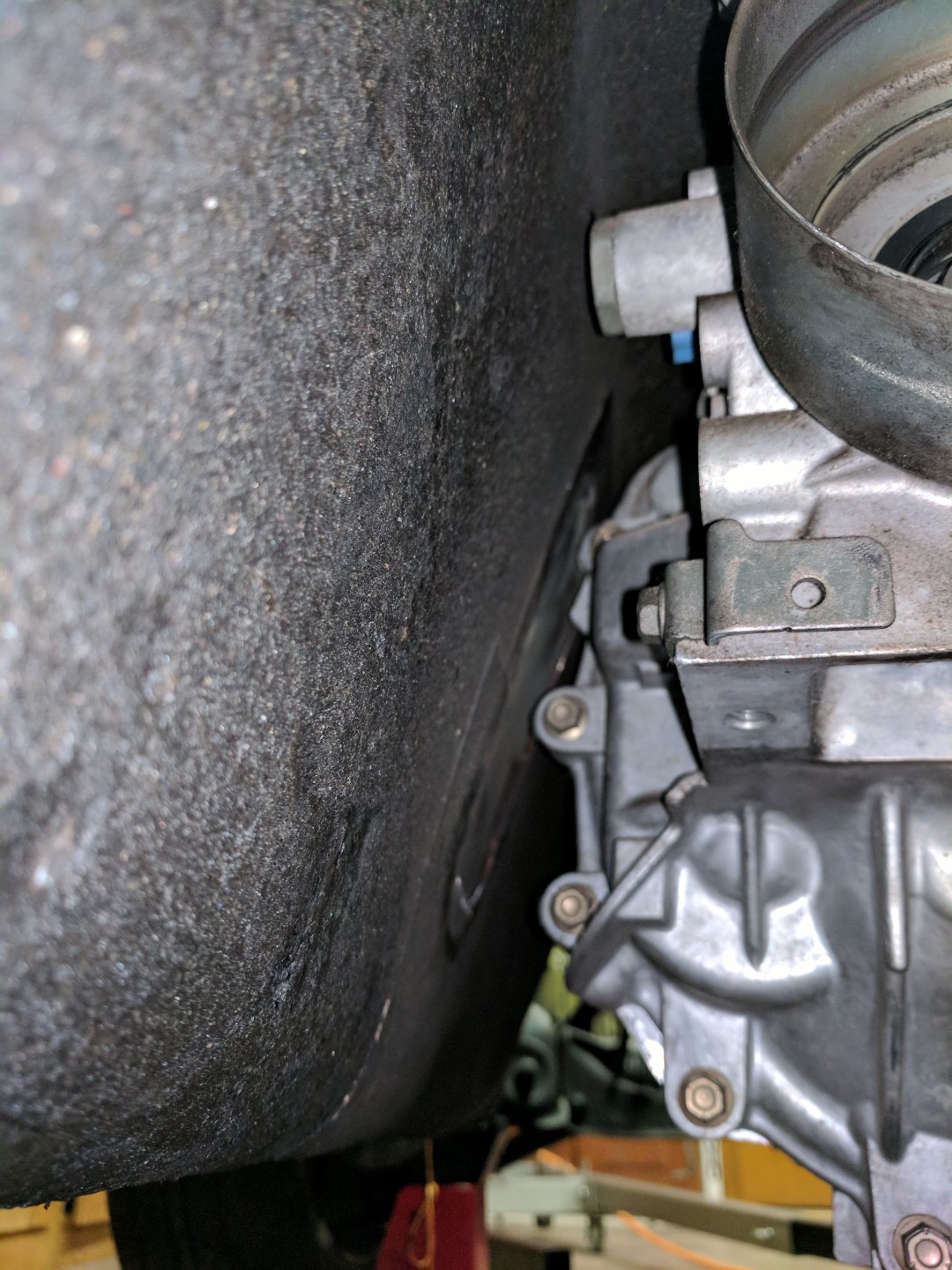
The transmission is quite large and fills up the entire 240z transmission tunnel with little room to spare! The factory transmission mounts must be removed. This is a messy task but not very difficult. An angle grinder with a cutoff wheel can be used to remove the mounts, the remaining flanges acan be smooth down to the tunnel sheet metal using a sanding disc. The pictures below also provide a nice visual of the shifter rod location.


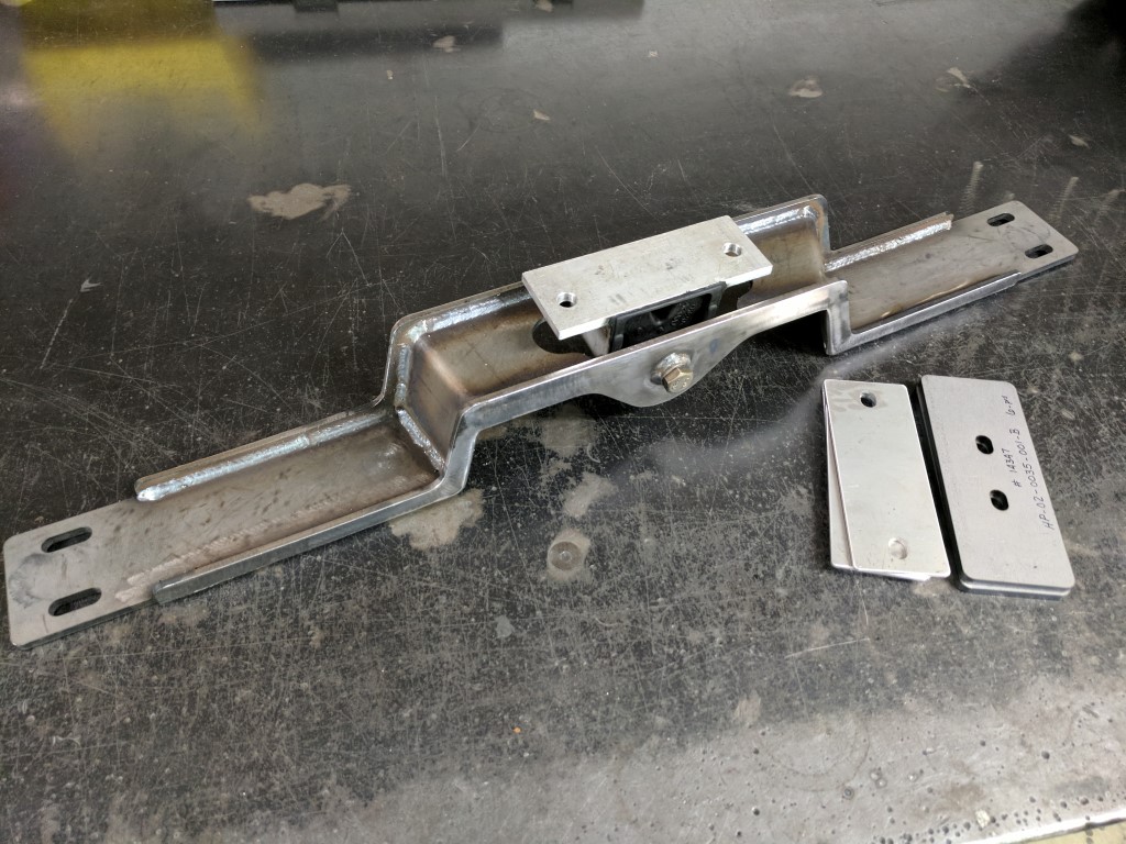
After playing around with a few concepts and taking some lessons learned from our LS kits I decided on a design which mounts directly to the frame rails and utlizes the 350z transmission mount.


The first mount went out to one of the beta testers, the Z Car Garage of San Jose. While putting together the standard beta kits we chatted about getting a 6 spd in their TC24 vehicle for 2017 JCCS. This was an exciting opportunity and I was happy to help with the build. Due to the DOHC head the engine actually leans the opposite direction of the standard L series so we put together a custom plate for Rob, the timeline was tight but we made it happen. When the kit arrived they were ready to rock and roll...everything bolted up smooth and they got the transmission in the car quickly. With some long hours they finished all the other modifications and made it to JCCS to became the first 6spd L series car to hit the streets!! These guys are great to work with and I really value there feedback. (Keep reading to see how this design has been updated for the initial production run!)


With the exicting news of the ZCG vehicle hitting the streets attention was turned back to the shop installation and supporting the other beta testers as required. With mockup complete and the transmission mount finished the engine was pulled back out for final kit installation. The block was cleaned up a bit and given a fresh coat of paint to match the shiney bits about to be installed.
The original dowel pin and bushings were removed from the block. A new alignment bushing is pressed into the adapter (already installed on the kits) and a new alignment dowel installed in the block. Next the old pilot bearing wass pulled and replace with the new offset version, it is definitly worth investing a few bucks for a pilot bearing puller...the adapter is only 15 dollars and makes removal a snap.


Before mounting the plate to the engine the transmission bellhousings needs to be modified slightly to provide clearance for the spur gear, this process the covered in detail further up the page so Ill skip the details here.
After the bellhousing modification is complete the adapter plate was installed on the block with (4) M10 FHCS, these are installed with loctite 242 and torqued to 30ft*lbs. The new flywheel bolts in place like stock, new OEM bolts were used and are included with each kit. The starter was installed next, 3 washers are used under the mounting bolts to provide proper thread depth allowing for full thread engagment on the plate without sticking out.


Rounding out the engine prep was the clutch installation, any L-Series clutch may be used and mounted. High grade metric bolts with norlock washers are included with the kit to mount the pressure plate. A standard clutch disk alignment tool may be used as well. Dan chose a ACT clutch with a 6 puck sprung disc.
With the clutch installed the next step was to bolt up the transmission! My little helper stepped in to assist. The transmission should slide easily into place over the adapter studs and onto the alignment bushings. Apply blue loctite to the studs, then install the washers and nuts, there are also two bolts that thread into the bottom of the adapter. Tighten the nuts to 30 ft*lbs and the lower bolts to 20ft*lbs


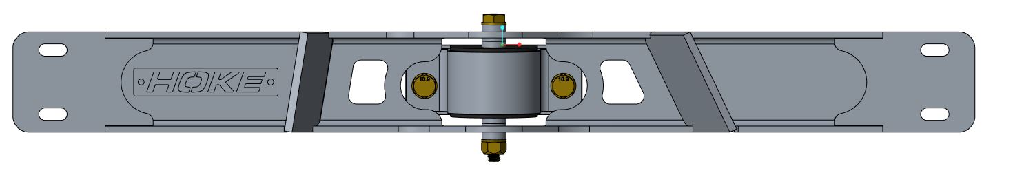
When putting the first batch of full kits into motion I sat down to make a few small adjustment to the transmission adapter based on some feedback from the Z Car Garage. I was about to wrap it up when I decided to change up the design entirely, a few late nights later and I had a new version finished. The new design allows for more exhaust clearance (which is at a premium!), less welding, and lighter weight! The design to made from laser cut from mild steel and will be finished in black powder coat. Our logo will cut from a thin piece of stainless steel and bolted in place. More info further down the page!

Back to Dan's car, the next step was final engine installation. Everything went smoothly, here is a look at the CBF shifter and where the shift lever is located inside the car. Only a small amount of trimming was required around the shifter opening and the lever will work with the factory console and shift boot. I plan to work with CBF to put a small offset in the lever but it works well as is! (update: CBF has include a 1" shifter offset and revised their design to include a sheet metal base as well)


The crossmember installs was next. Using a floor jack to hold the transmission and mount in place 4 holes were drilled up through the frame rails. Inside the passenger compartment backup plates are installed to distribute the load. Dan's car had some significant floor damage presumably from a lift accident and due to this I had to make some custom spacers between the mount and the frame rail. Note that the mount should typically sit flat against the frame rails. Shims are provided with the kits that may be placed between the isolator and the transmission to alter angle, the norminal shim height is 0.375" or 3 shims, four 0.125 shims are provided with the kit. The goal is to match the engine angle and the differential angle.
Please keep in mind the initial design crossmember design is shown in these pictures which is replaced by the design shown above for the kits. The crossmember is also powdercoated black and backup plates are zinc plates.
A 'Ron Tyler' differential mount is always suggested with moderate to high horsepower builds which also has the advantage of lowering the differetial angle slightly to around 2 degs, this in turn provides a little more ground clearance at the transmission by raising the tail.
Driveshaft installation is straight forward, bolting in like stock. We use driveshafts made by the Driveshaft Shop, they are local to us in NC and have built their reputation on high performance drivetrain components. Standard material is steel but aluminum and carbon fiber may be made on special request.


With feedback coming in from beta kits the first production batch was made. Thse kits should typically be in stock and will continue to evolve from feedback as required. As always if you have questions please contact via email!


I can also assist with putting together transmission packages if required, especially for international customer where part availability may be scarce. Please contact for more details