This project started as a customer build and after surverying the market and even purchasing another kit we decided that we wanted a better solution. The goal was to design a bolt in kit with OE fit and finish, we wanted the engine to look like it came from the factory and have the drivablility you expect from a modern engine. That project is now complete and burning rubber arond NC, please see the project vehicles page for more information on that car and the rest of the LS integration. LS kits are now sotcked for both 240 and 260/280z applications! Please see the store for pricing details and purchasing options.
Our development build used a 1972 240z and a LS2 from a GTO were used for development, all LS blocks share the same bolt pattern however making this kit aplicable to any version of the engine. The main differences are in the oil pan and front accessories. These kits were designed using CAD and all components are laser cut, bent, welded on fixtures, and finished with black powedercoat. All high grade yellow-zinc coated hardware is included for installation. An engine crossmember core is required.
Kit Features:
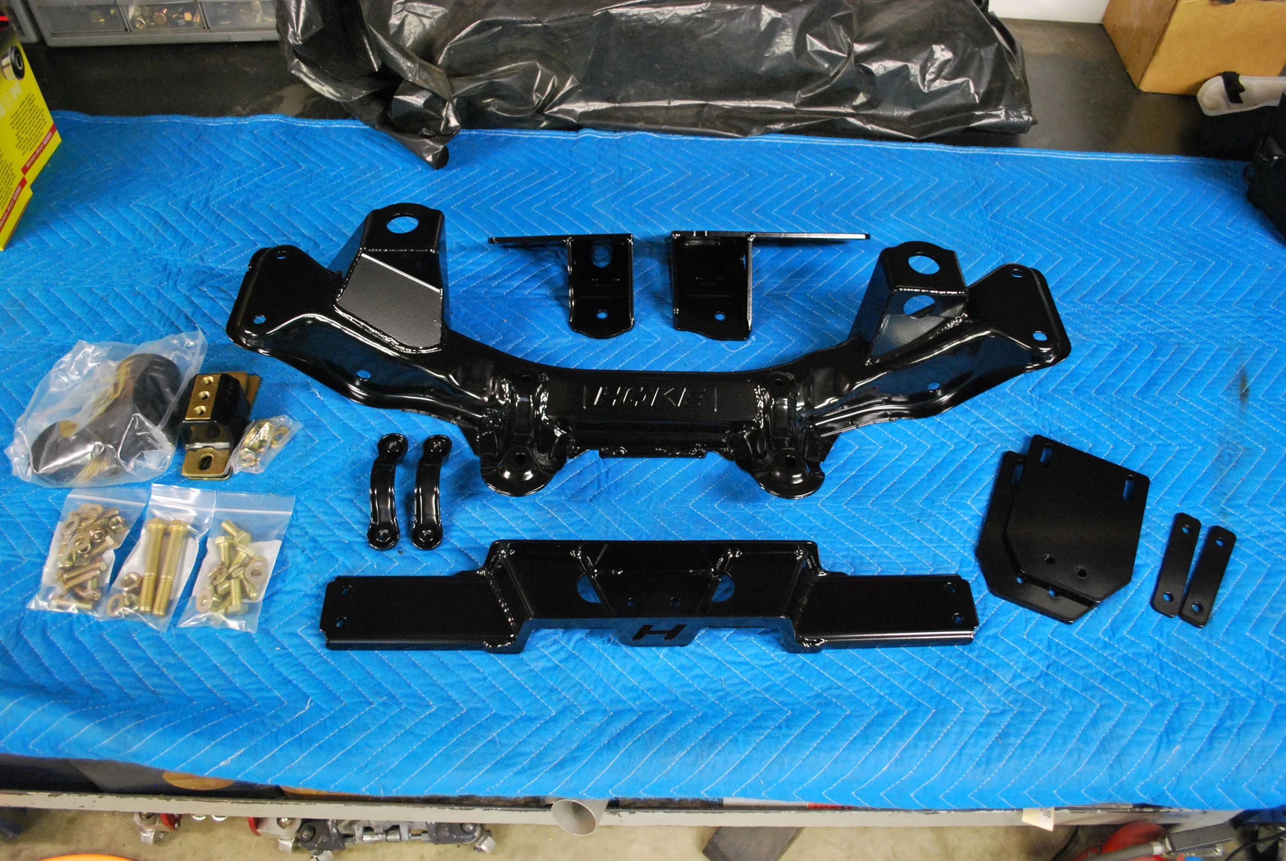
- Bolt in Mounting Kit for Any LS Series Block w/ T56 Transmission
- Engine Crossmember (Core Required)
- Engine Mounts, F-Body and GTO Front Accessory Options
- Transmission Mount, 240z and 260-280z Chassis Versions
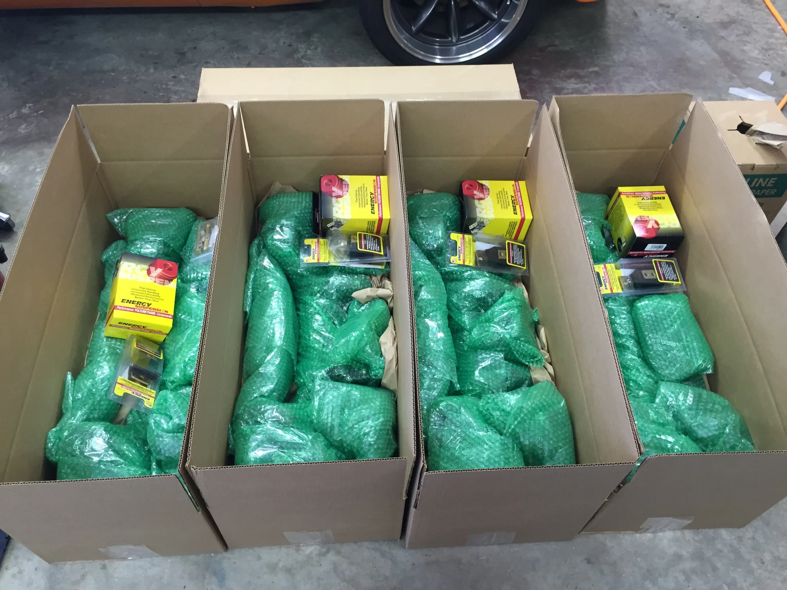
- Energy Suspension Polyurethane Isolators and all Hardware
- Driveshaft optional with versions for both 280z and 300zx R200 Flanges
- Professional Welded On Fixtures and Finished in 80% Gloss Black Powdercoat
- LS2 Corvette Oil Pan Reccomended (GM PN 12581810)
- Compatible with Hawk's Thrid Gen Long Tube Headers and CX Racing Long Tube Headers
- Please contact to discuss automatic transmission mounting
Our Development Vehicle completed and on the road!
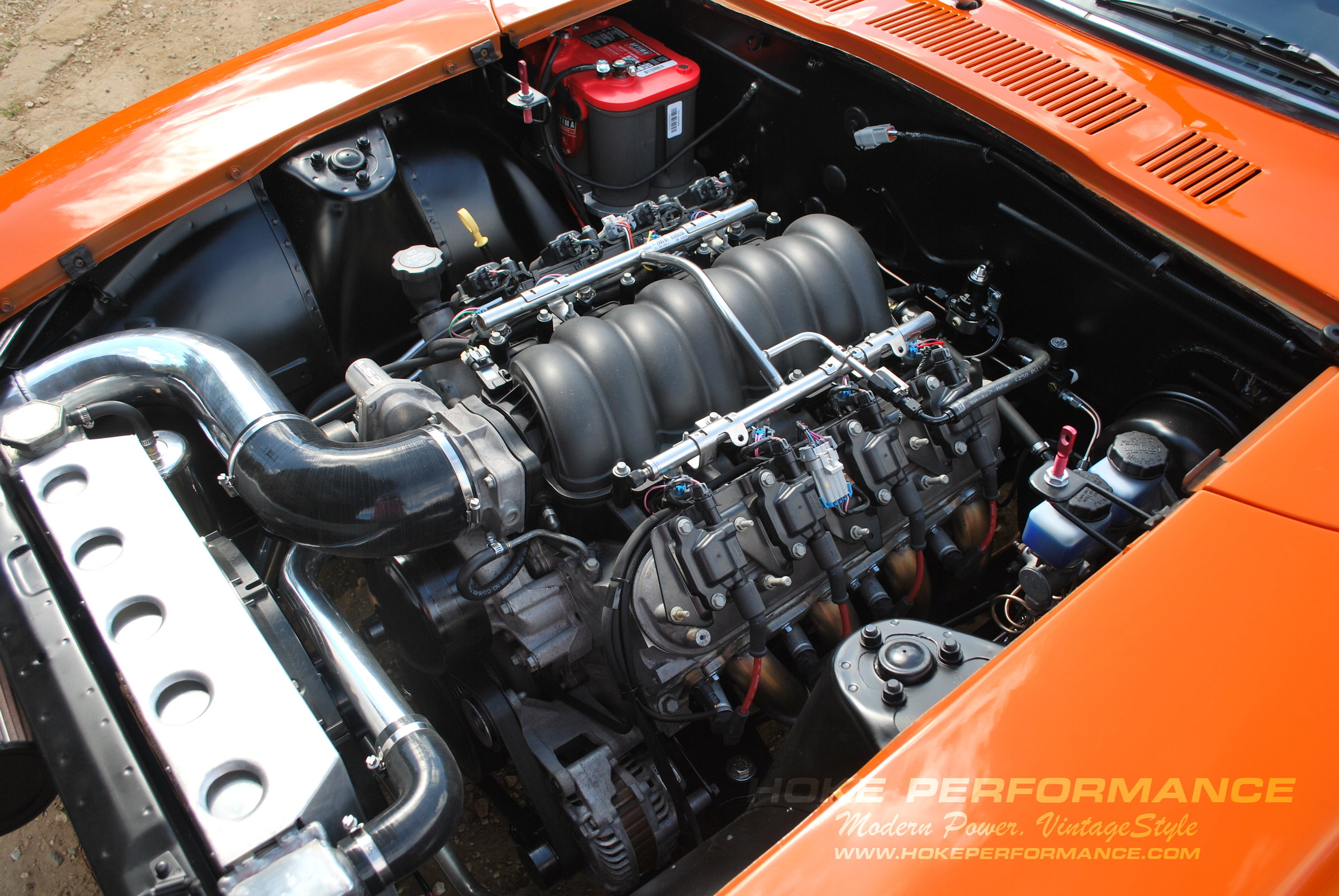
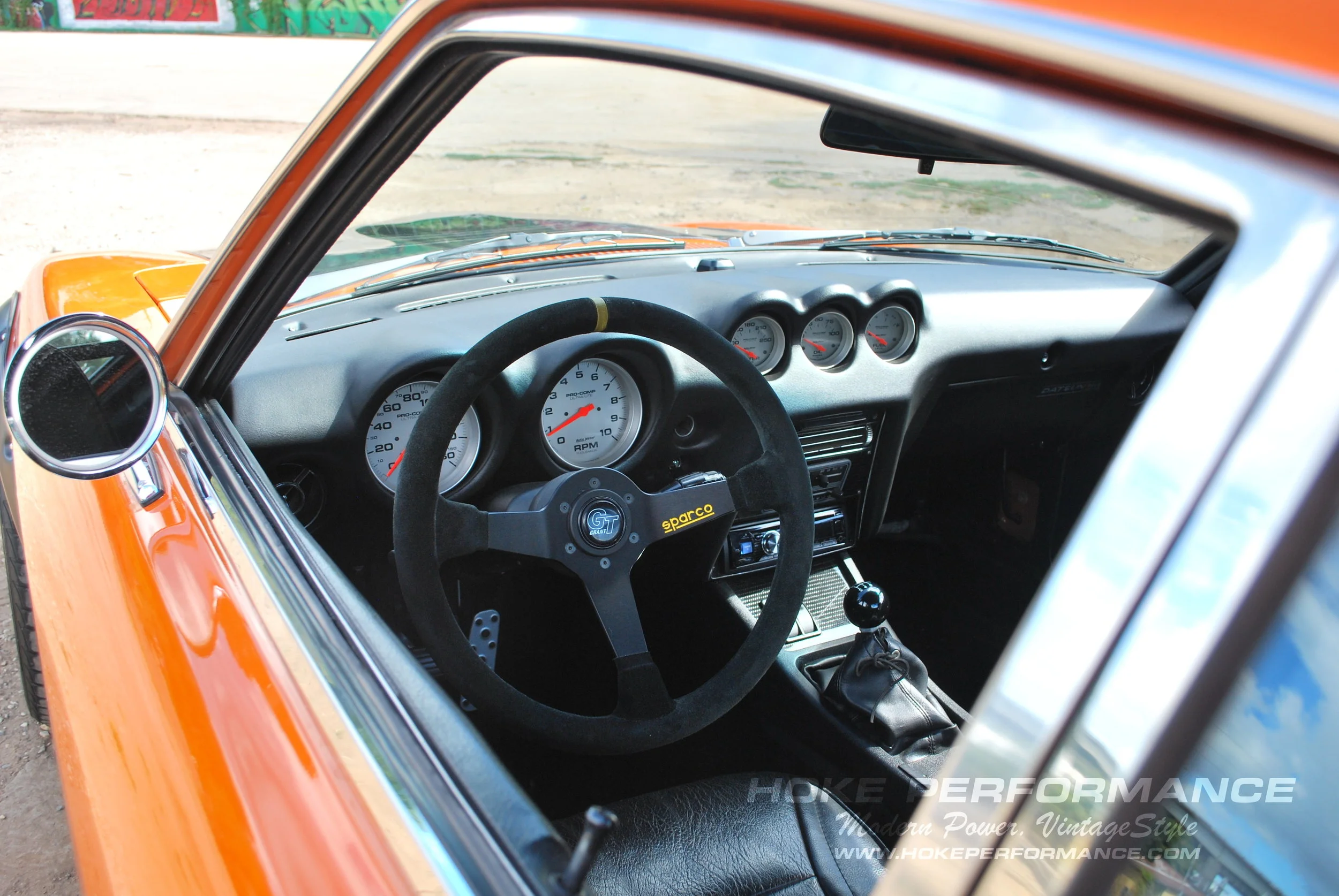

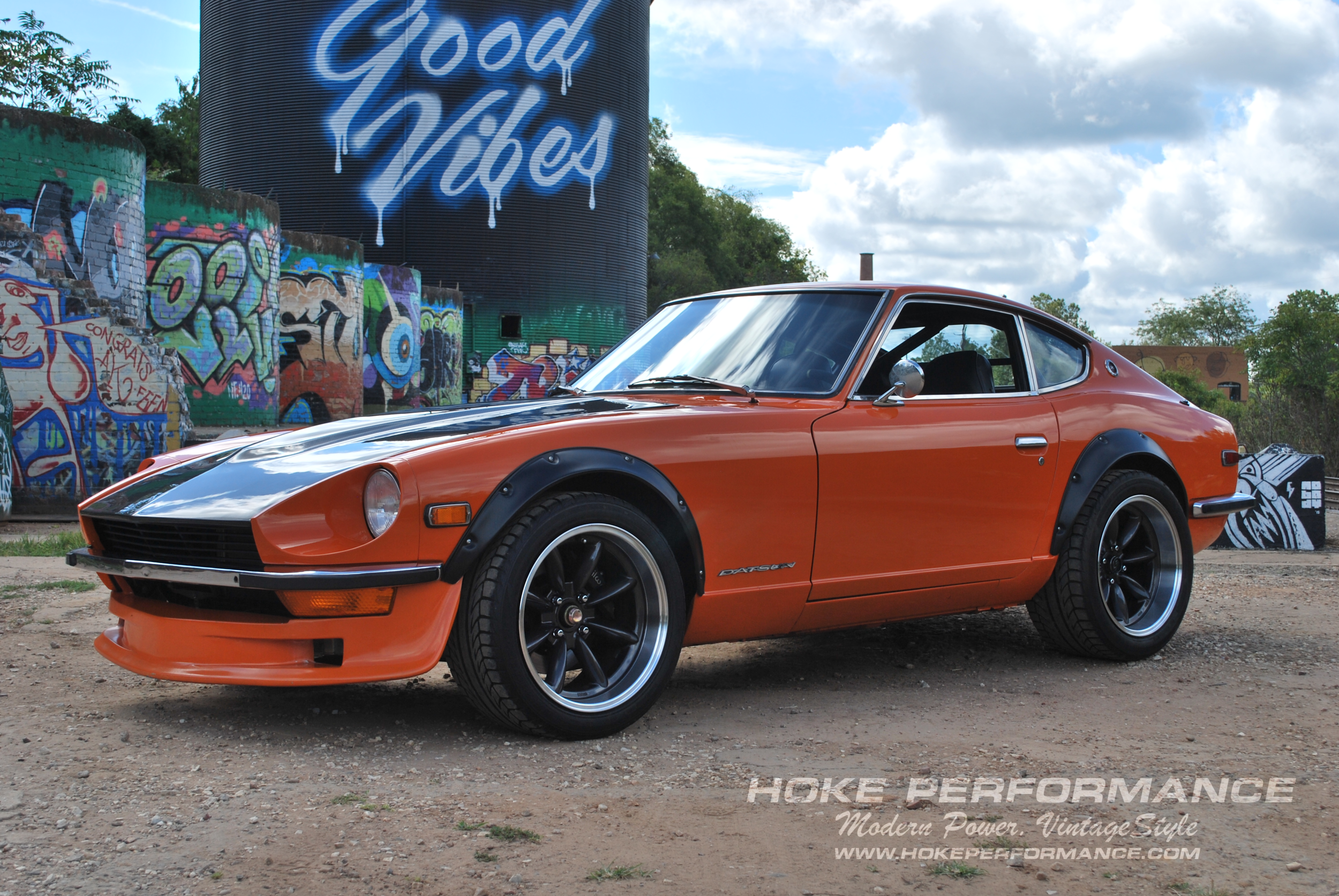
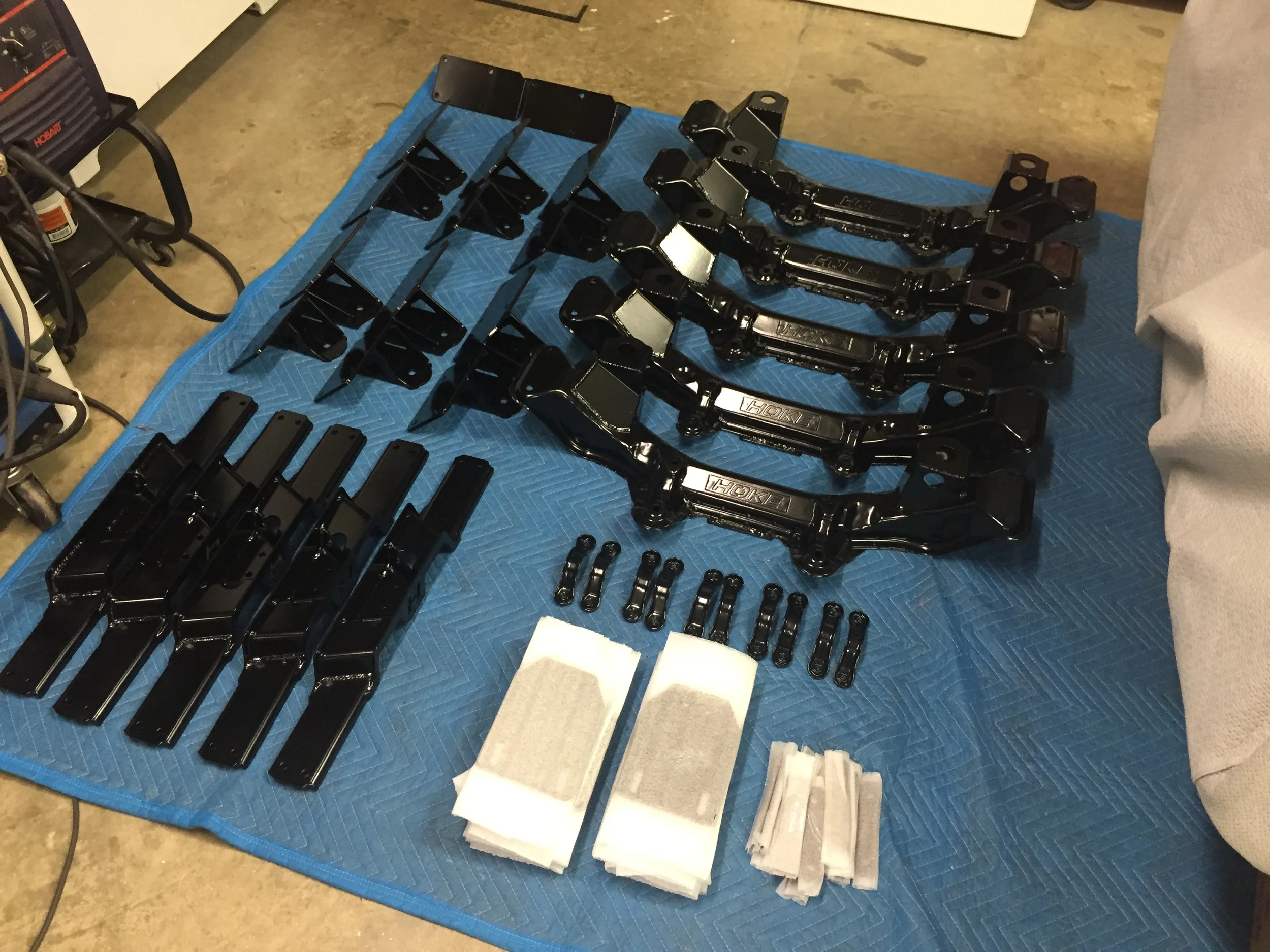
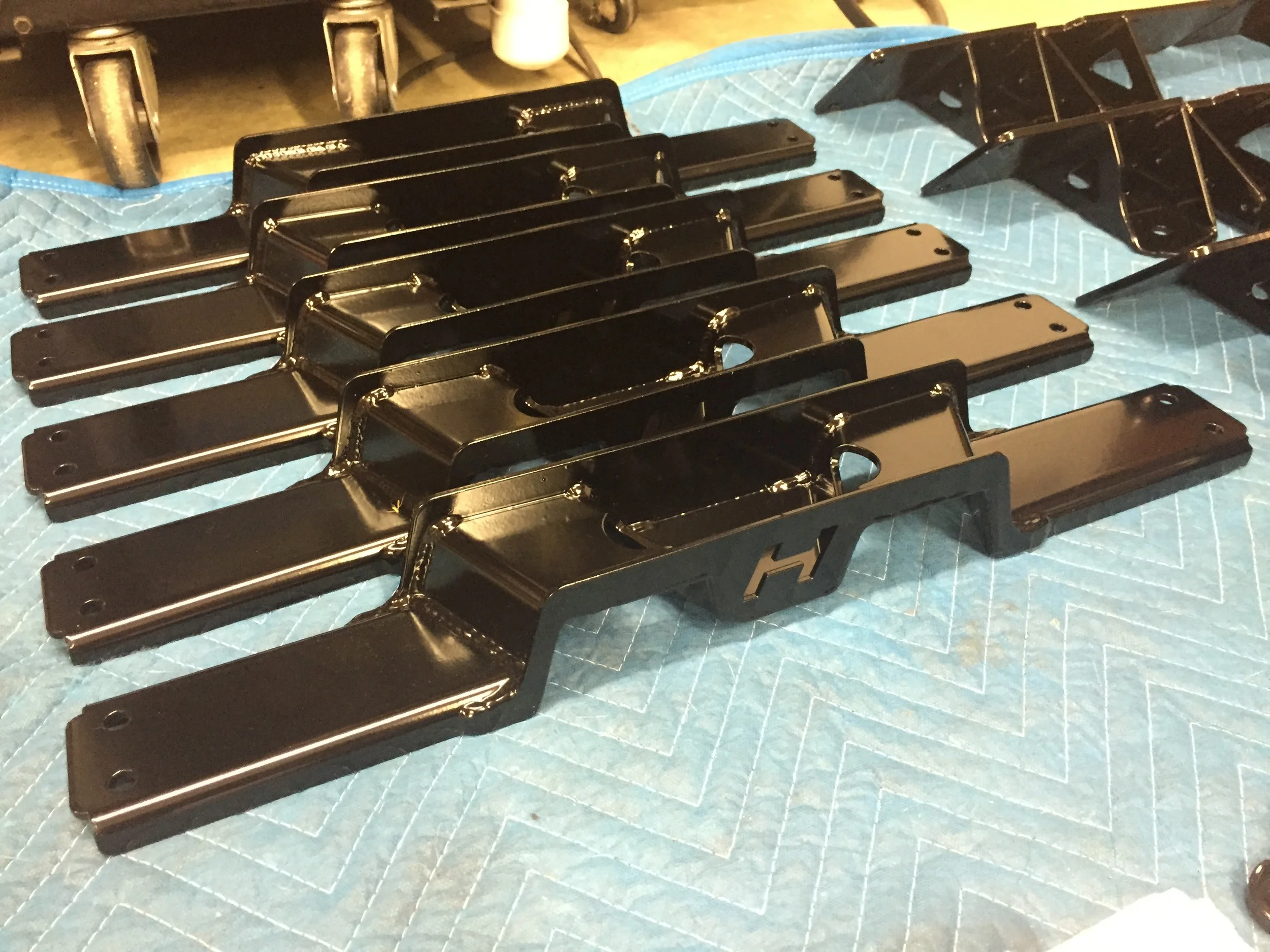
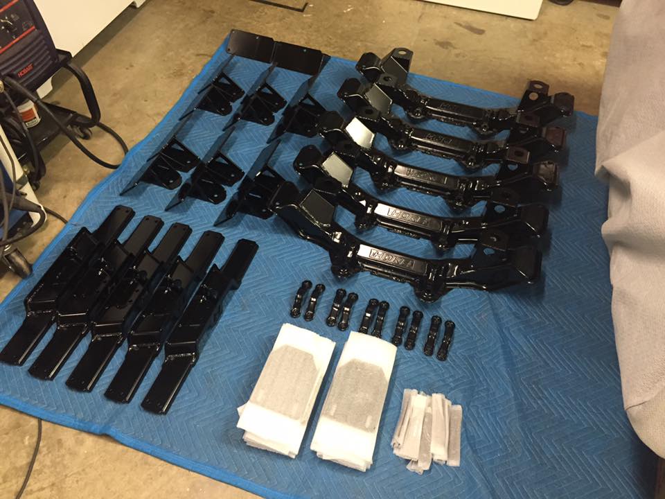
First batch of production 'Beta' kits (LS2 Engine Mounts and 240z transmission crossmember shown):
DEVELOPMENT PROCESS:
The development car for this mounting kits is owned my a good friend and customer Matt who is a long time Datsun enhusiast. Being built in my spare time we knew it would take a while but we both wanted to do it right and that started with the development of a new mounting solution! Matt sourced the engine from a LS specialist on ebay, we were impressed with how clean the engine was the professional packaging job, everything needed and more was included to get the engine running. We quickly went to work stripping the engine of parts we didnt need and getting it cleaned up for test fitment.
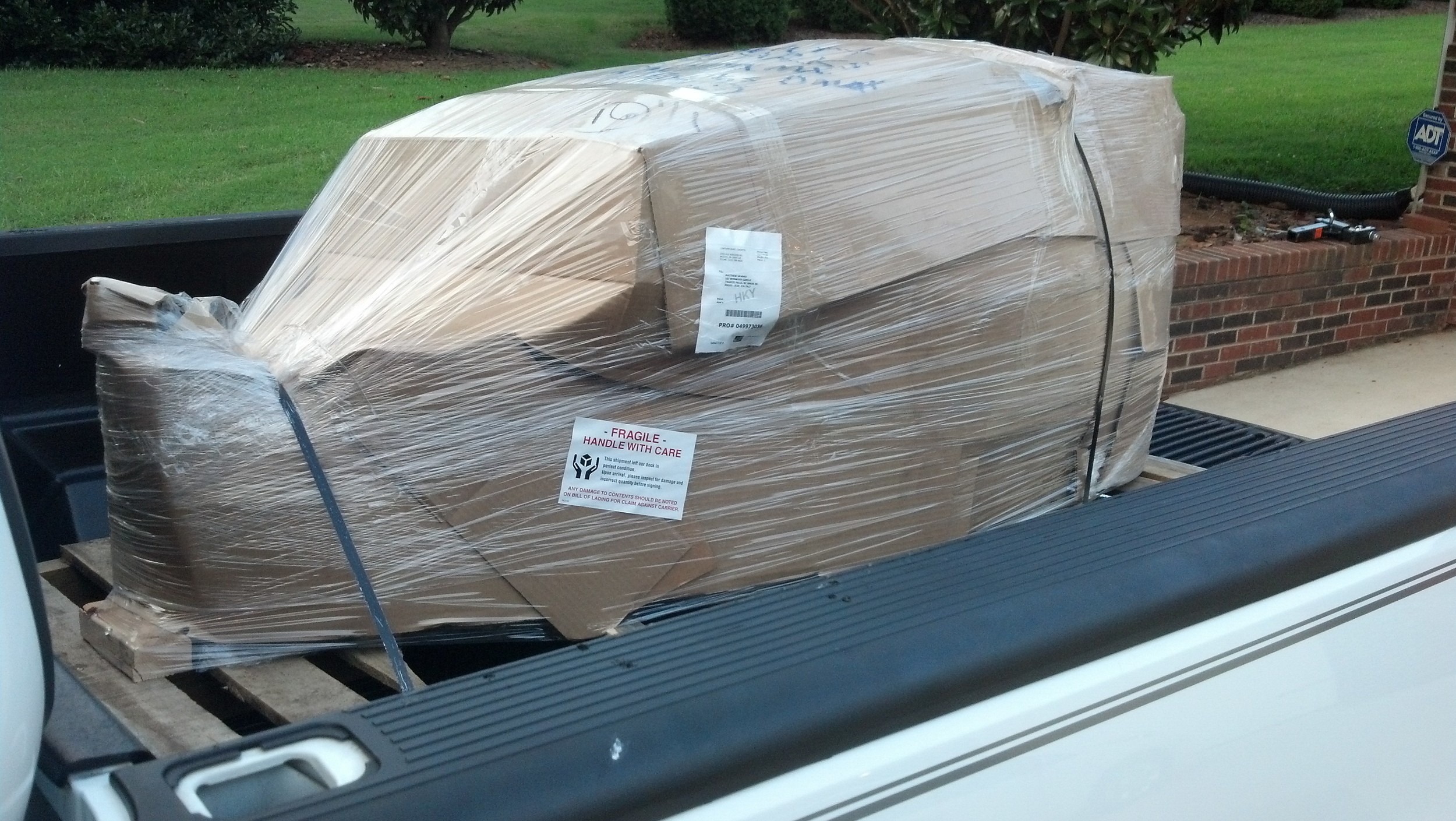
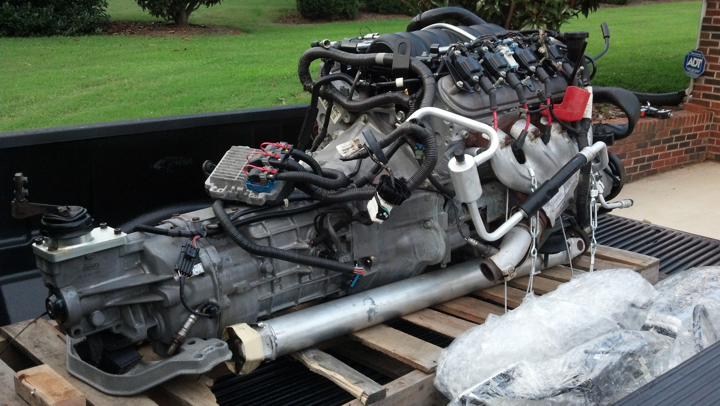
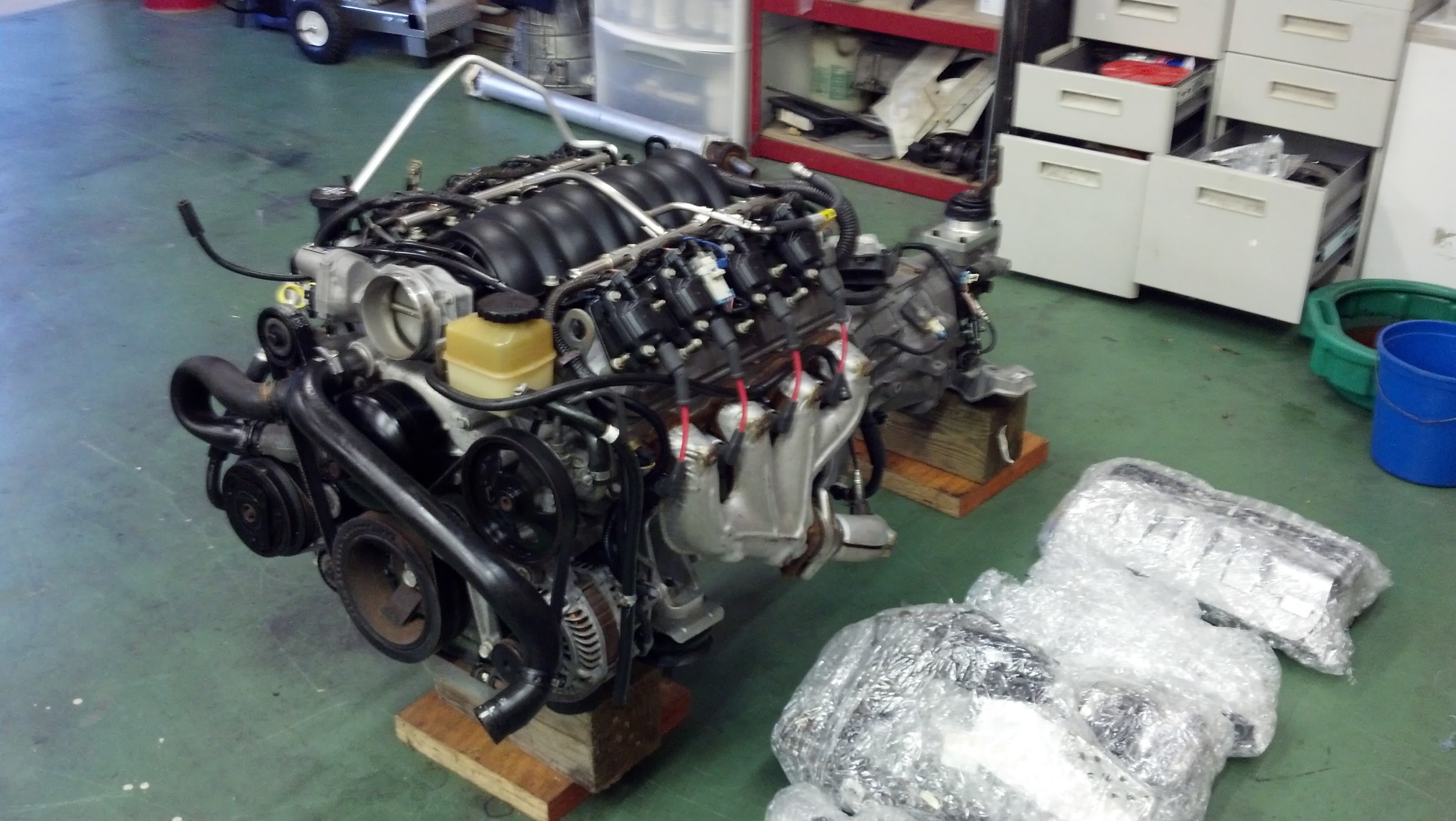
The GTO oilpan has a deep sump with would present ground clearance issues so it was swapped for a Corvette LS Oil Pan. This pan was choosen due to it's internal baffling and clean design. In addition to the pan a matching windage tray, oil pickup, and dipstick are required. These can be purchased directly from GM or found readily online used. Ours was purchased off ebay and were removed from a new aftermarket engine. The F-Body and Vette pan are nearly the same dimensionally and both can be used with the mounting kit.
This is a great link for further oil pan information: https://ls1tech.com/forums/conversions-hybrids/817787-lsx-oil-pans.html
With the engine stripped down and the pan installed I called up my local go-to souce for laser scanning, Dittberner Engineering. The owner, Dan, is a great guy to work with and we scheduled a day for him to come over and scan the engine along with the engine crossmember. The scanner used is extremely accurate and capable of capturing 3D data that can be used for design work. Scanning is time intensive especially at higher resolution, We focused on capturing the engine and transmission mount locations and well as the head port dimensions, the rest of the engine was scanned at a lower resolution for packaging purposes. Below are a few pictures of the scanning process.
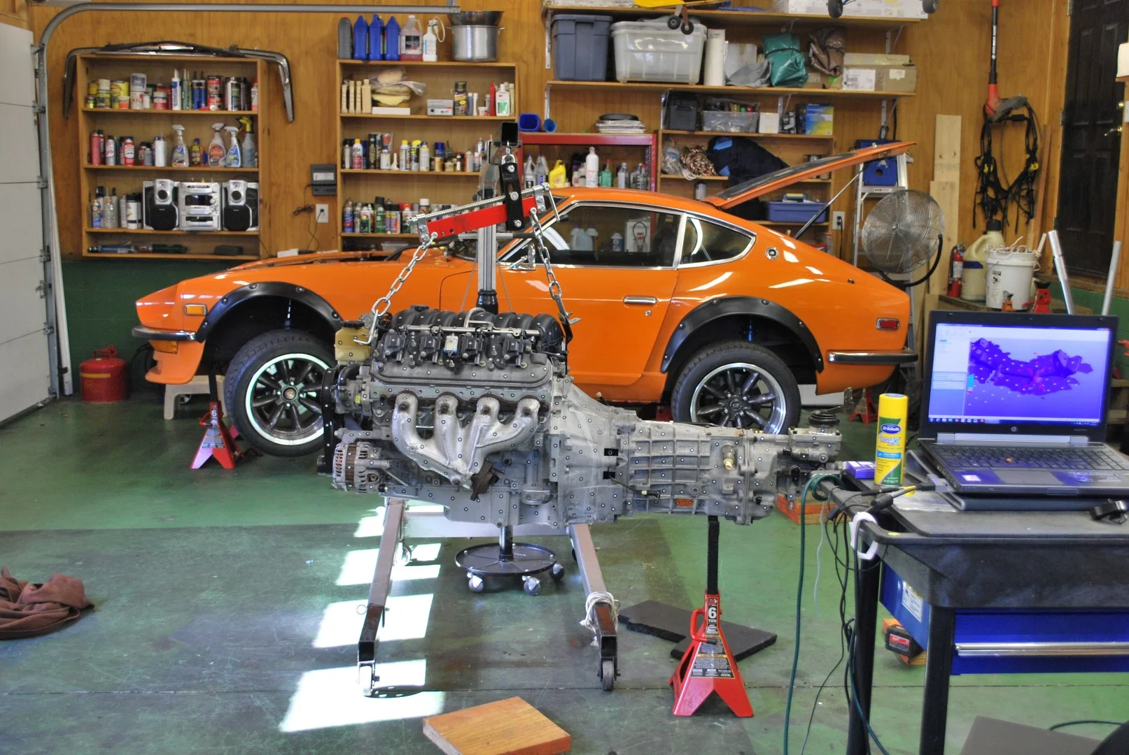
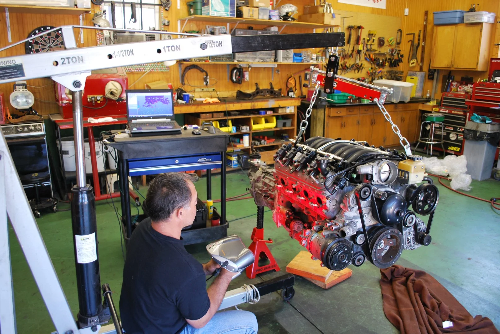
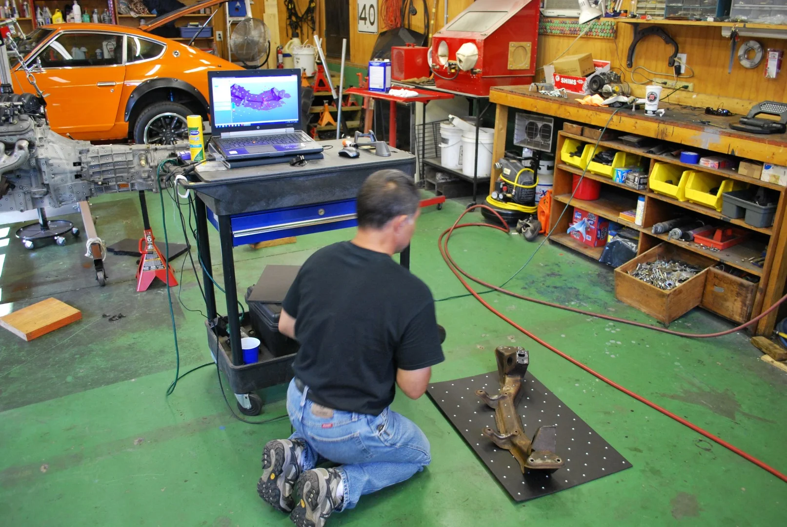
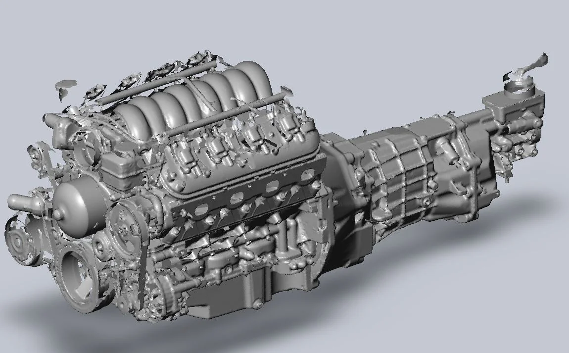
3D scanning is an excellent design tool. The result is a cloud of points which are then turned into a STL file, these files are comprised of thousands of triangles that connect those original points. The raw STL file itself is great for packaging but only as a visual reference. Getting this data though is often this the 'easy part' as converting the scan data into usable CAD geometry and surfaces is extremely time intensive even for skilled CAD users. In this case the bulk of the engine was left as raw scan data and critical features were extracted for design such as the mounting features and crank centerline.

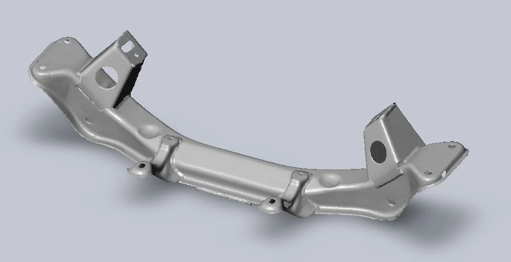
While much of the engine could be left as raw scan ata for packaging the corssmember needed to be reverse engineered into a solidZ CAD geomtry. Using 2D crossections of the scan a parametric model was created that matched the scan very closely. The original scan and the new CAD geometry is shown below.

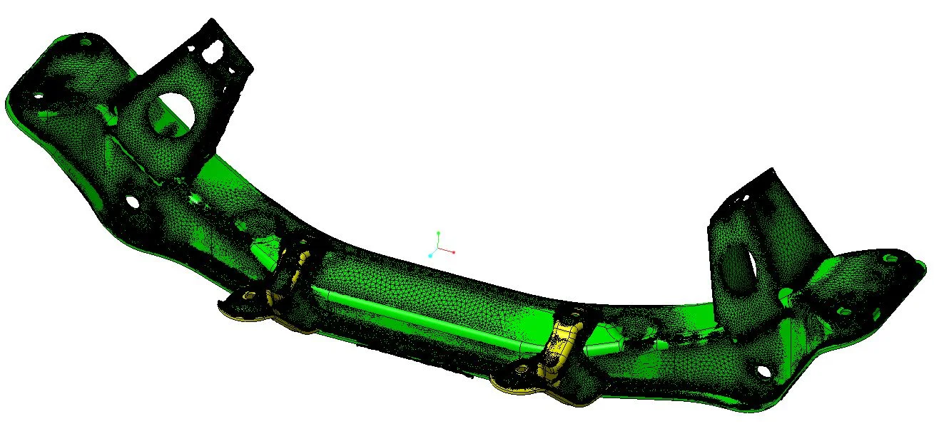
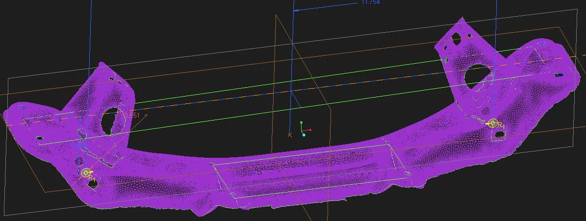
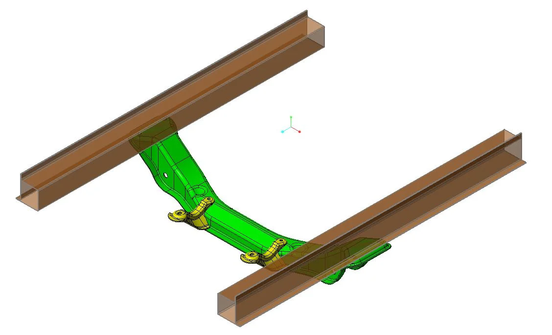
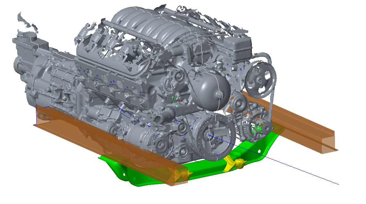
With the crosmember model complete and the datums in place for the engine hand measurements from the car were used to sketch the frame rails and locate the firewall and radiator crossmember. Using the frame rails, crossmember, and engine a packaging model was now complete which could be used for designing the new LS mounts.
DESIGN:
The the nessecary building blocks in place a combination of the CAD models and test fitment in the car were used to located the engine. The engine position is constrained by oil pan clearance to the crossmember, damper clearance to the steering rack, and header clearance around the steering column and firewall. We had the Hawk's Third Gen long tube headers on hand and wanted the mounts to be compatible with them, these headers are made by American Racing Headers and are nice quality for the price. Taking into account all these variables the engine placement was set in place. Measurements were taken to transfer the location into CAD, including the distance from the firewall, crossmember clearance, and engine angle. The corvette pan is placed 0.25" above the crossmember. The screen shot below shows fore-aft placement, the dotted lines represent the radiator crossmember and the firewall.
Initial mockup showed that the larger GTO alternator (as compared to F-body) would fit nicely without interferance from the frame rail or steering rack, although tight! The factory A/C compressor presented a challenge with passenger side frame rail interferance.
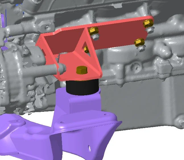
The for the first design iteration the factory GTO isolators were explored, however they were quckly abandoned due to their bulky size and the desire a new more universal mount which could be provided with the kit. The first iternation allowed for the design to be roughed in, parts wre 3D printed to check fit and clearances. Below are a few images from this first iteration.
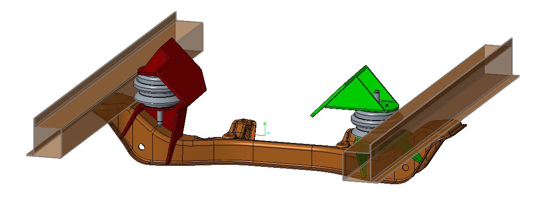
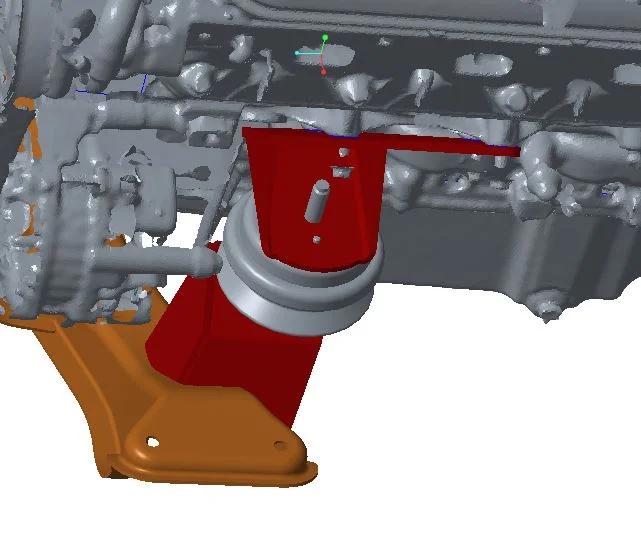
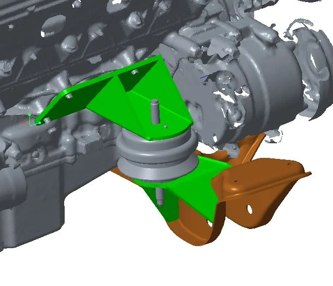
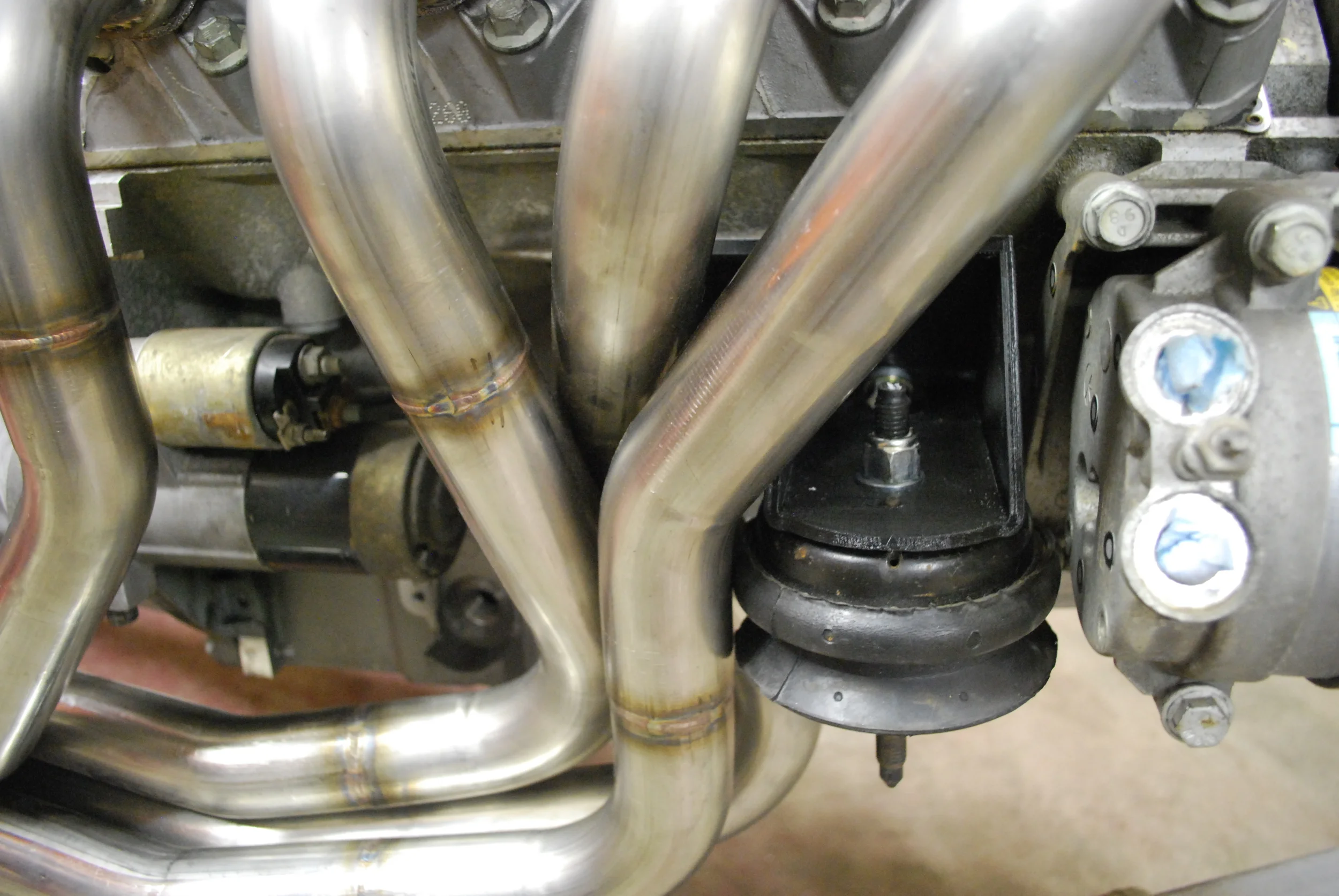
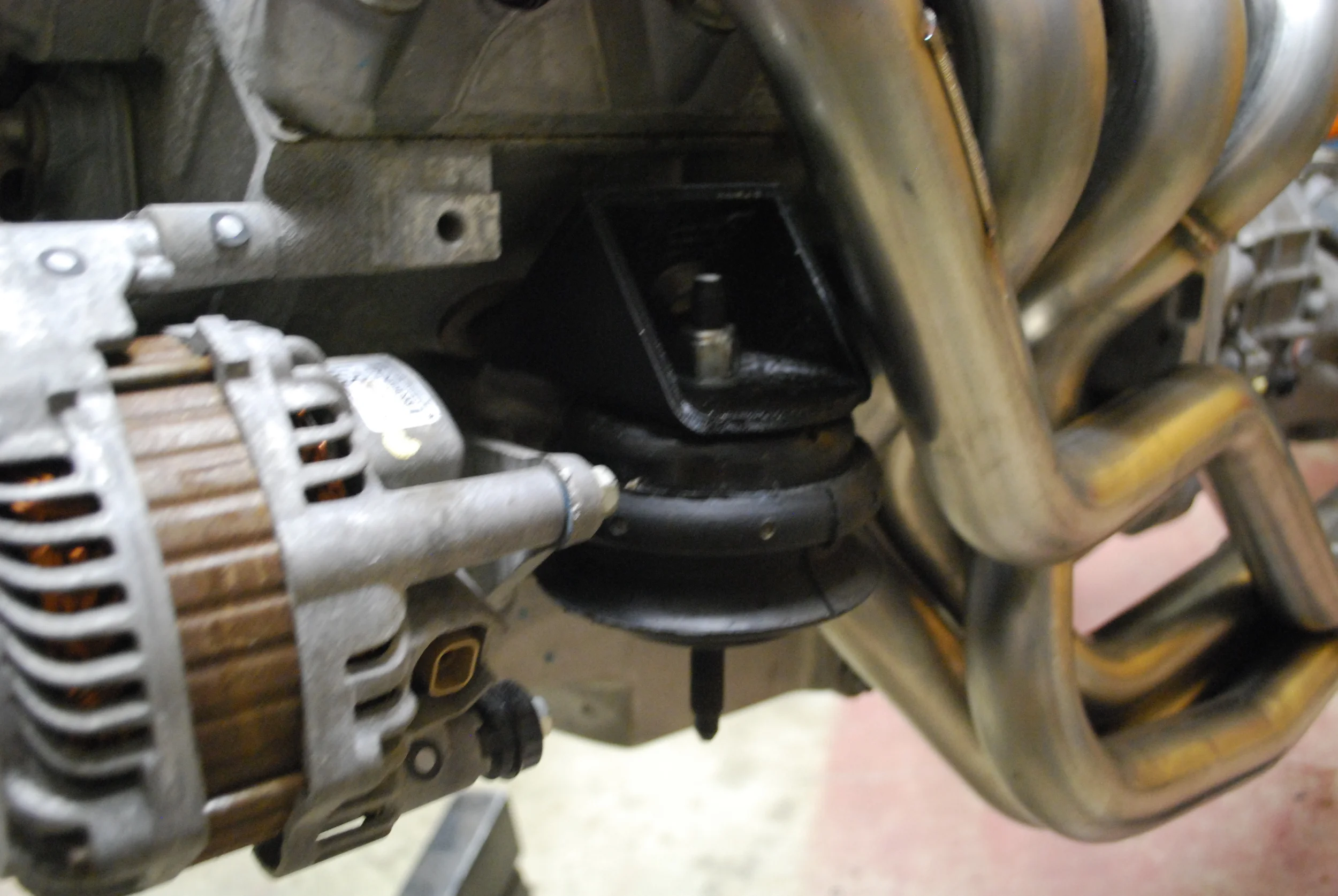
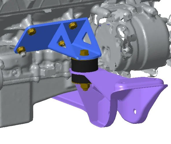
Moving to the next design iteration Energy Suspension isolators (9.4102) were choosen for their compact design and reasonable price. Compared to hoizontal bushings the vertical design provides additional damping and makes installation of the engine easy. This iternation was similar to the first but these more compact isolators allowed the mount to tuck in tighter providing more clearance for the headers.
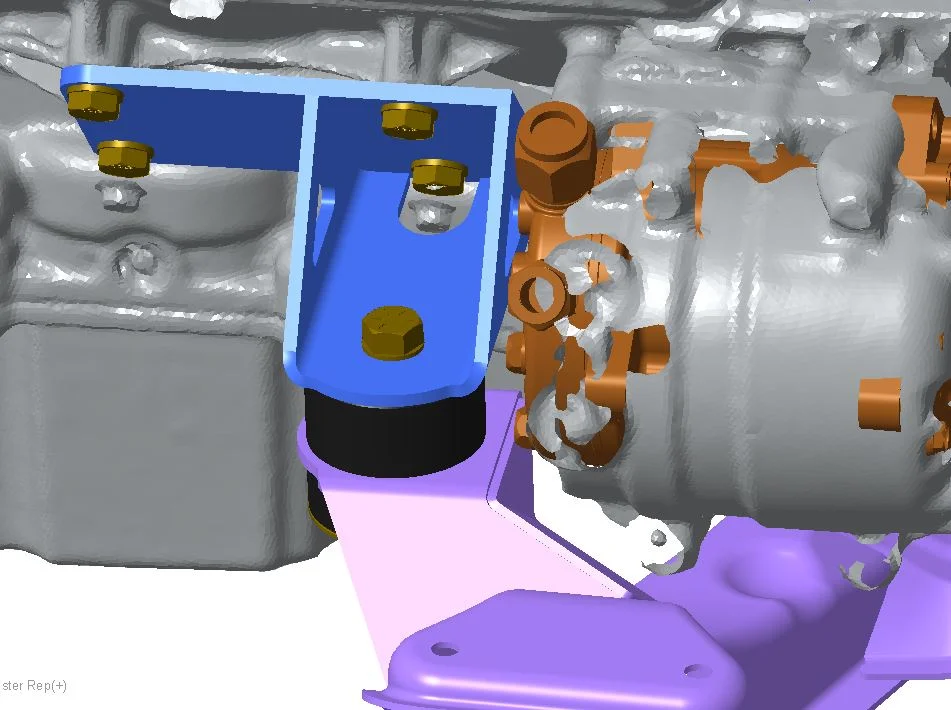
The passengers side engine mount was designed to clear the factory a/c compressor, as well as an aftermarket Sanden unit which is used for Vintage Air setups. To use the factory A/C compressor the frame frail would need to be notched. The more compact Sanden unit could be packaged with a custom mount which is planned for furture development.
Two versions of the drivers side engine mount were designed. On specifially for the OE LS2 alternator and another for F-Body (and others). The GTO alternator had a larger rear support strut which interfered with engine mount location, this strut is removed support is provideddirectly into the mount.
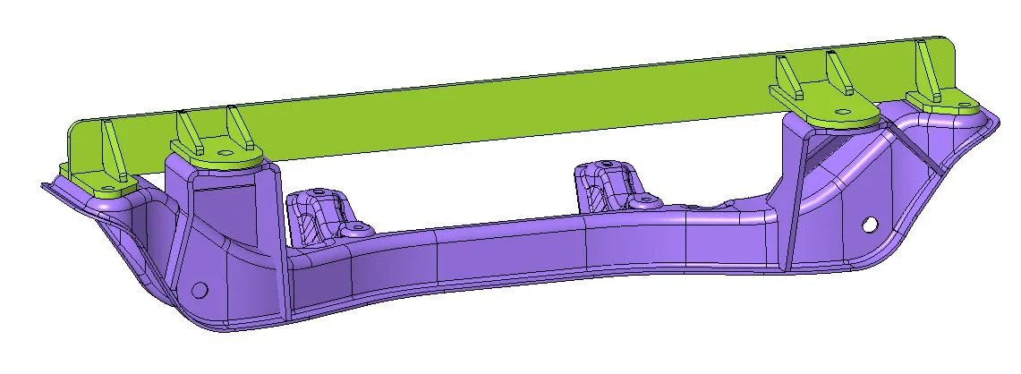
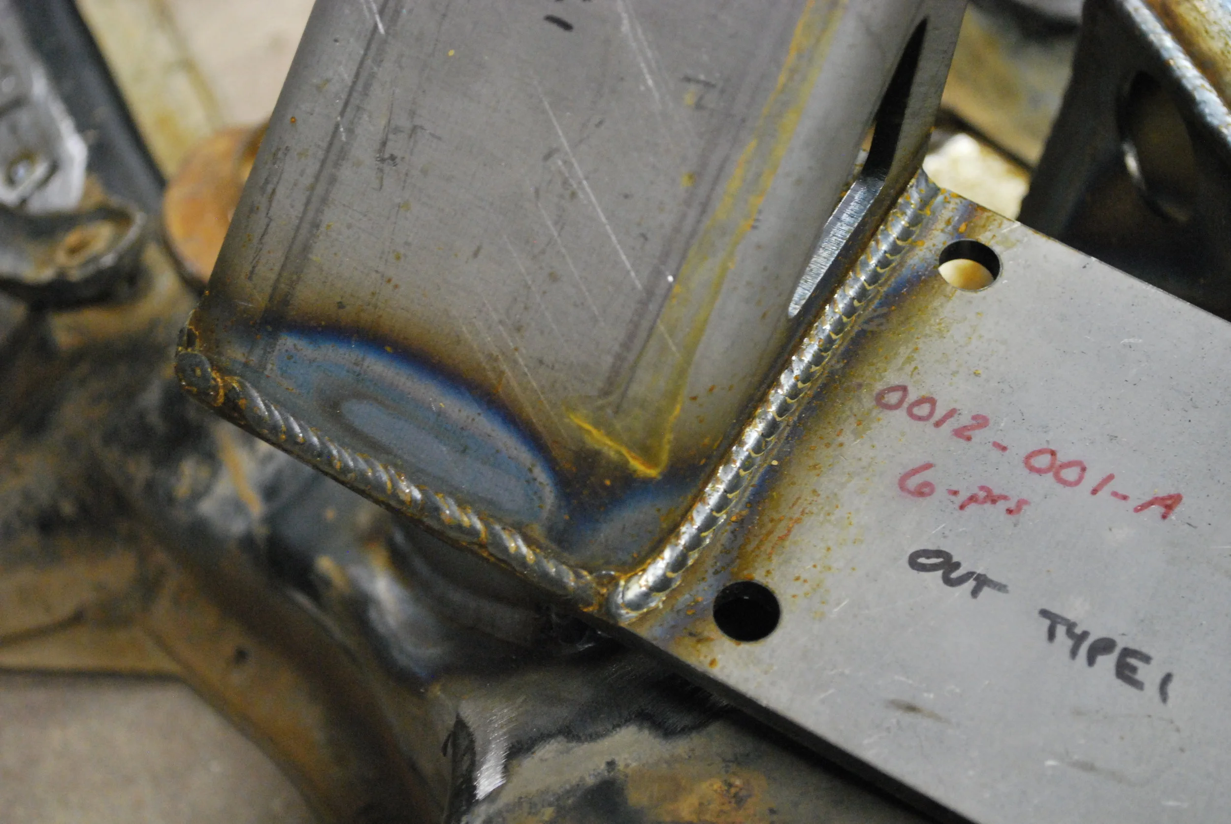
The design is based on a factory crossmember with the original engine mounts removed and replaced with new ones. The new mounts are precisly placed using a fixture to ensure perfect fitment everytime and the assembly bolts into the chassis like stock. No addtional labor required for fitment to framerails of a 40 year old car. This process does reply on cores which are kept on hand through an exchange process.



Attention was then turned to the transmission crossmember. The transmission tunnel is tight tight on the S30, especially after fitting the larger T56 6speed in place. Using a similar construction technique as the engine mounts the crossmember was designed using laser cut steel which provides a strong and intricate shape that can be easily fabricated. The mount was designed to provide maximum ground clearance with a dual exhaust setup. pipes were mocked up in CAD to test the design (Check out the project vehicle pages to see our actual exhaust installation!)
With our development vehicle being a 240z the first mount was designed for this chassis. While the 280z can use the same engine crossmember the transmission tunnel, floors boards, and center frame rails are very different, making two versions neccesary. The 240z version is shown below which mounts directly to the floor. The mount is tied into the chassis but an internal reinforcment plate which saddles the frame rail, which is in ternal held in place on the outboard side using a backup place (see pictures below).
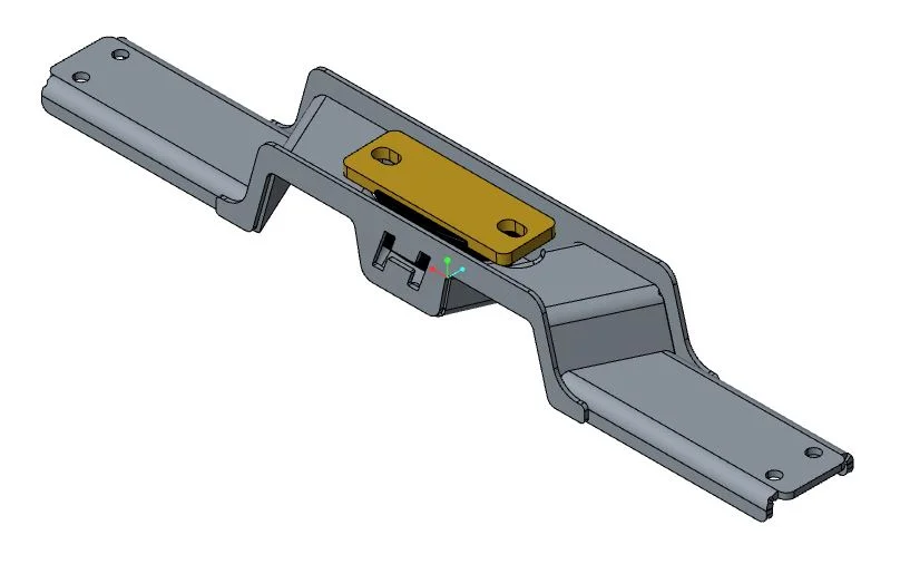
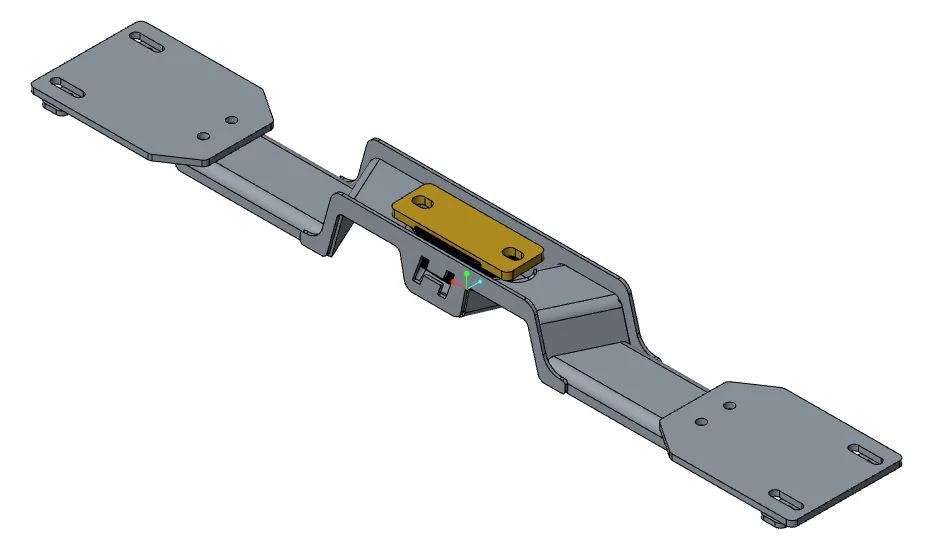
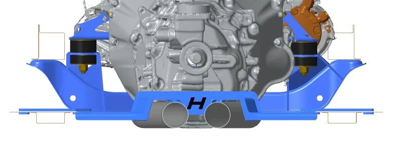
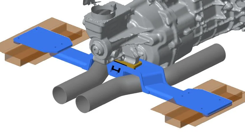
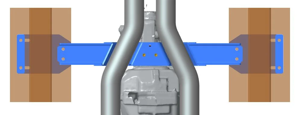
A seacond transmission mount was designed for the 260-280z chassis. The 280z floor board is stamped with more shape and also has fuel lines running along the pasenger side making the 240z mounting method undesirable. A new design was made to mount directly to the 280z frame rails which are larger and stronger then those found in the 280z. With this new mount the additional transission tunnel width was taken advantage of to provide more exhaust clearance.
With the prototype design complete prints were made and sent off to the laser cutter. The parts went together great, interfacing as expected with the engine crossmember. After tacking eveything in place the kit was fit to the engine and car for the first time. it is alway great to see a project start coming together!


With a succesful test fit final welding of the assemblies was complete sent to the local powdercoater. Thy did an awesome job applying a show quality gloss black finish to all the parts. One complete eveything was reassembled and the engine fit into place for the final time (maybe!).


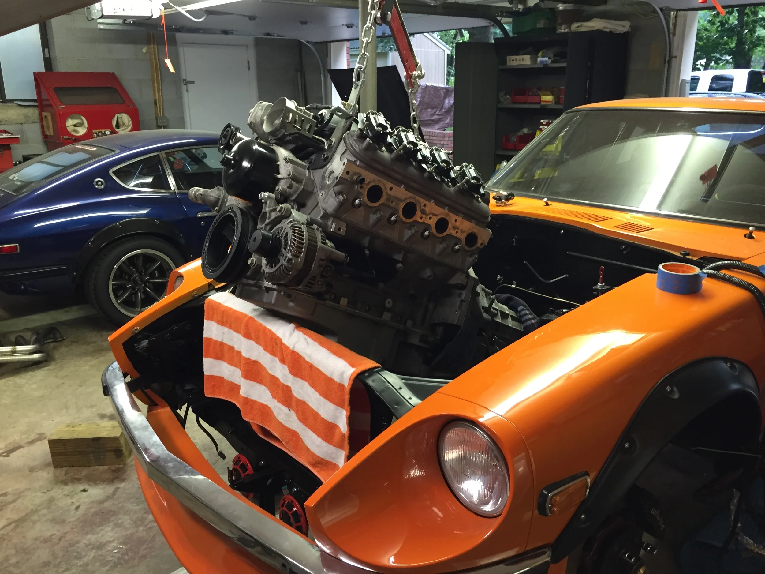
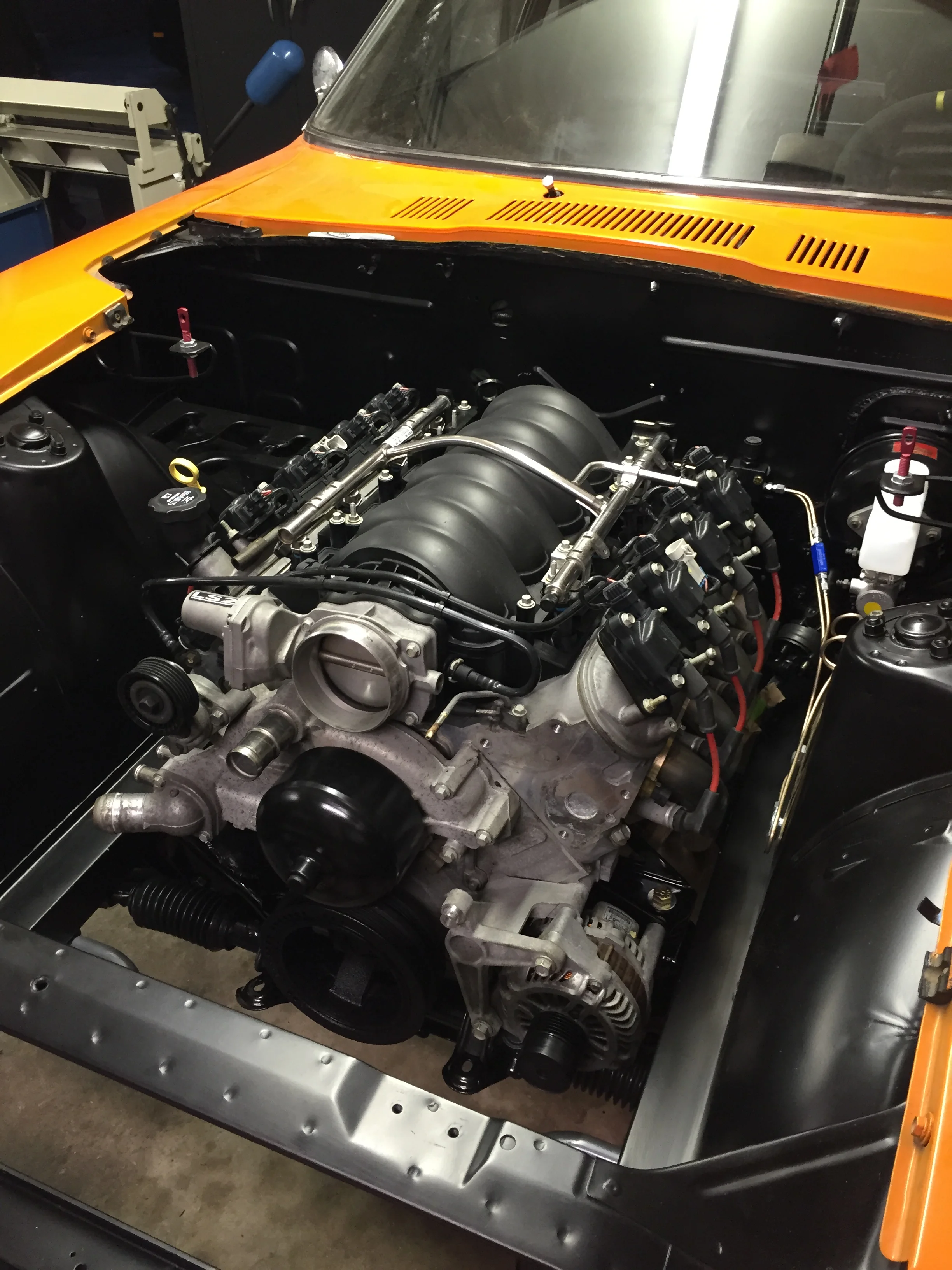
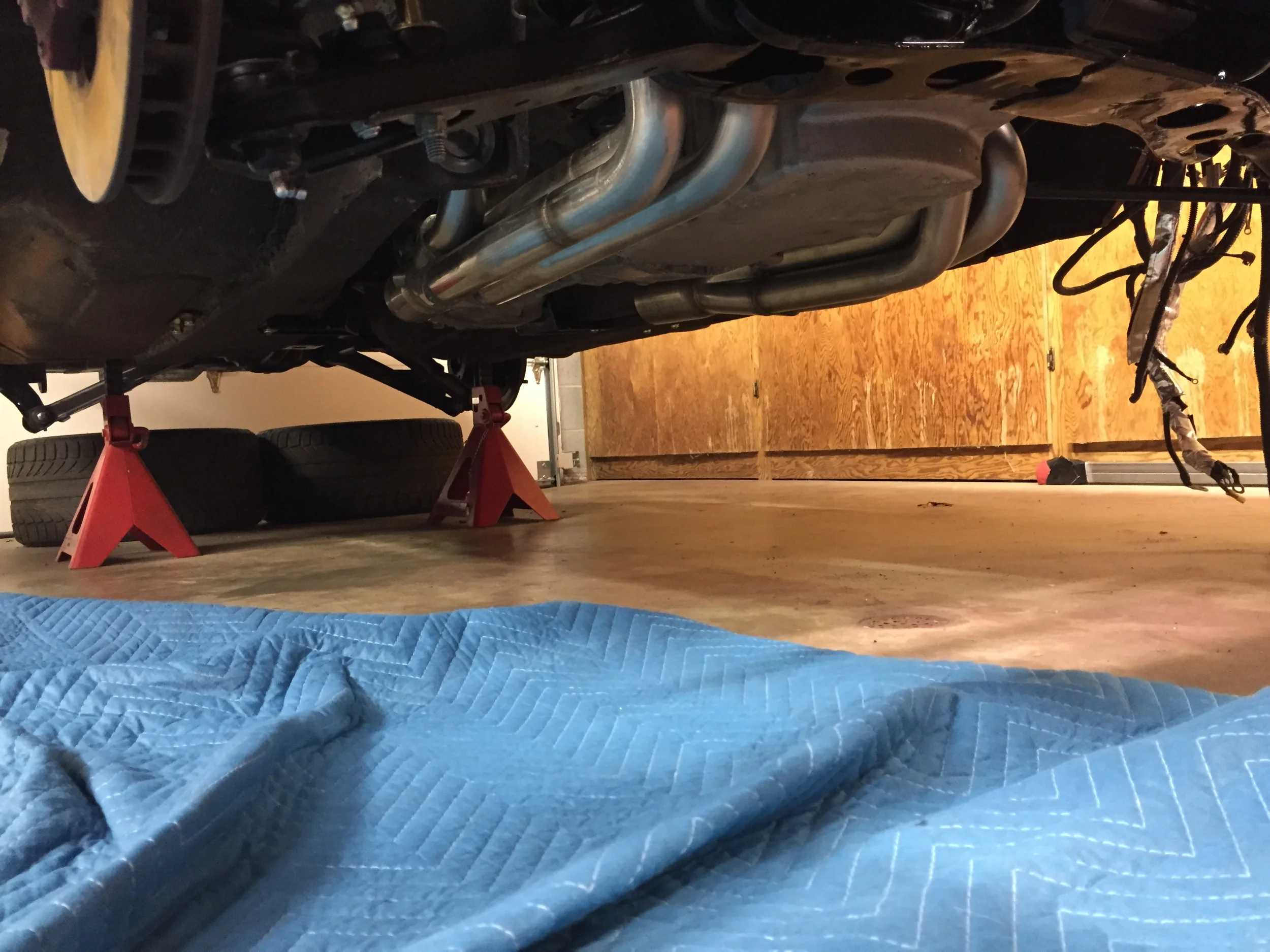


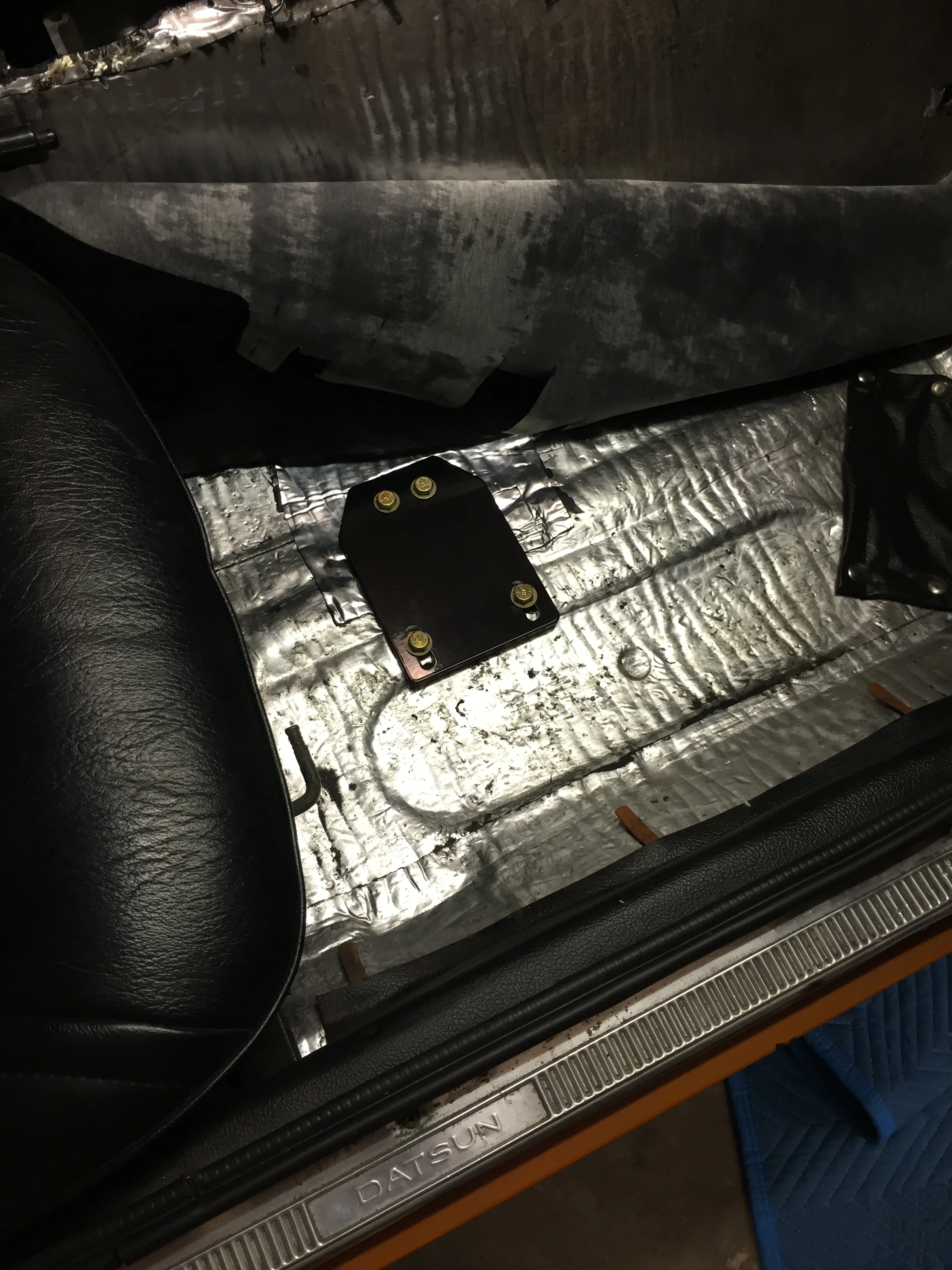

Work continued on the development car to finish all the remaining engne integration work, cooling, exhaust, wiring, etc. In parallel with this work on production kits continued in the back ground. Another iteration of transmission crossmembers was designed to better fit the factory unmodified tunnel and beta kits were assemblies for early adopters to test. Having only used our development car for fitment feedback from these installations were critical to verify and refine the kit.
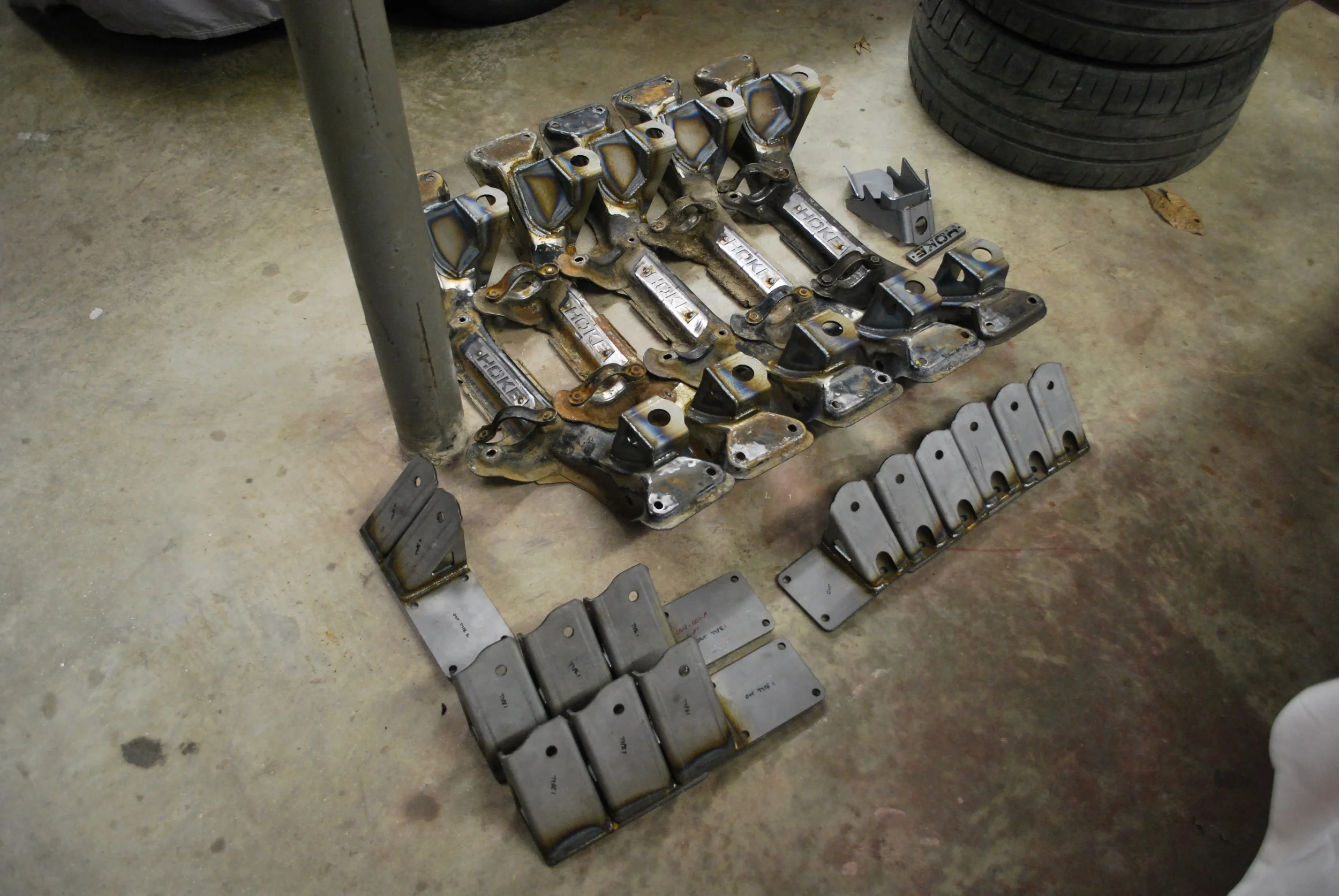
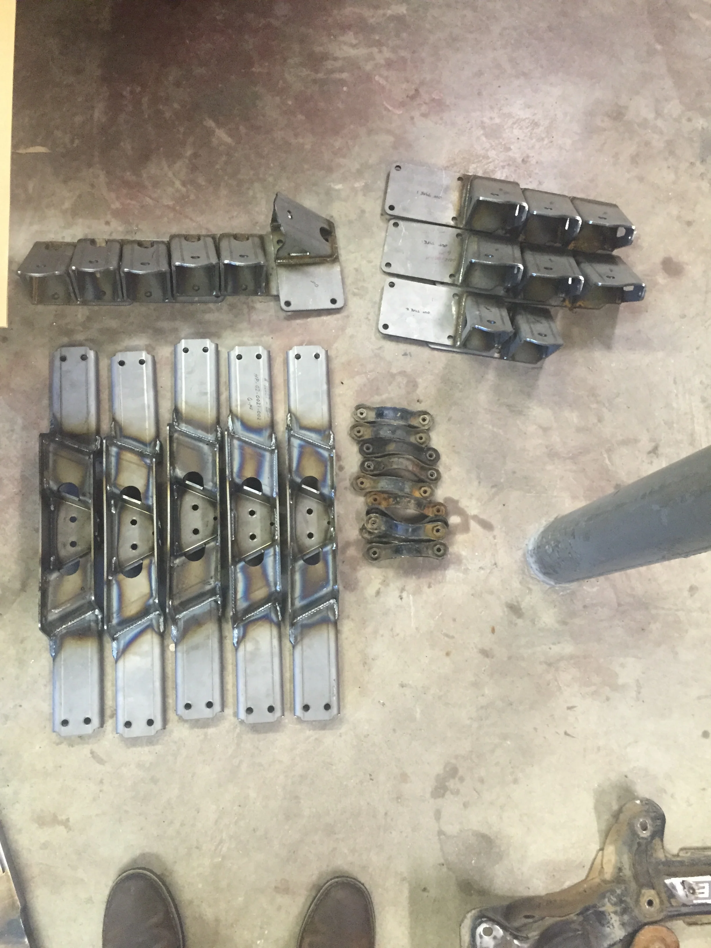
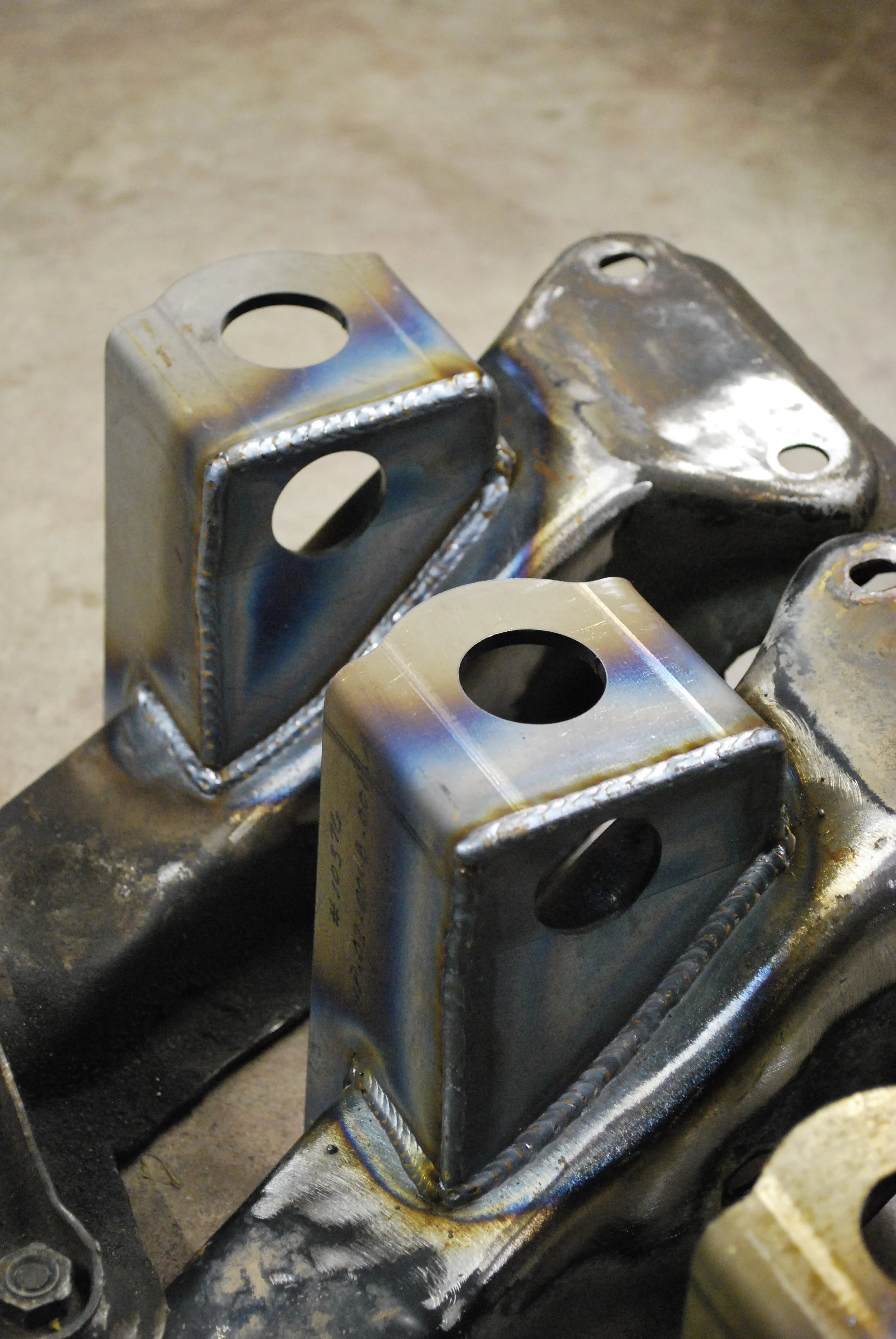
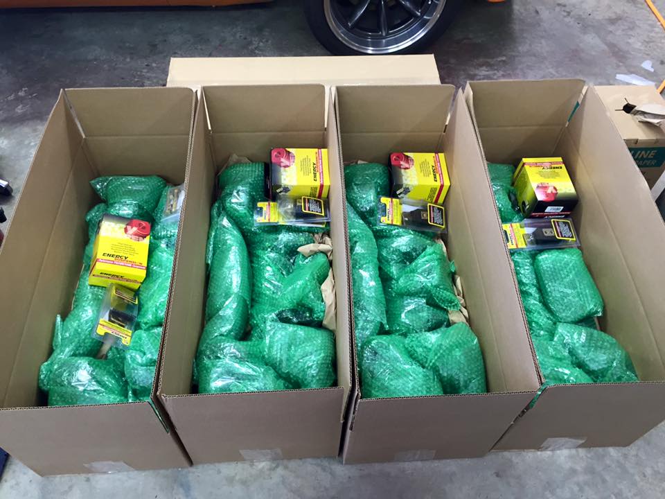
Seeing these kit getting installed into other vehicles was very rewarding, especially with the positive feedback received! We integrated a few small changes from the Beta Testers and now have these kits in 'production' and typically in stock. We wold love to be considered for your build, I believe you wll find the quality and design of our kits the best value currently on the market.
Please contacnt me via email to hokeperformance@gmail.com with any questions, feedback is also always welcome and appriciated!

