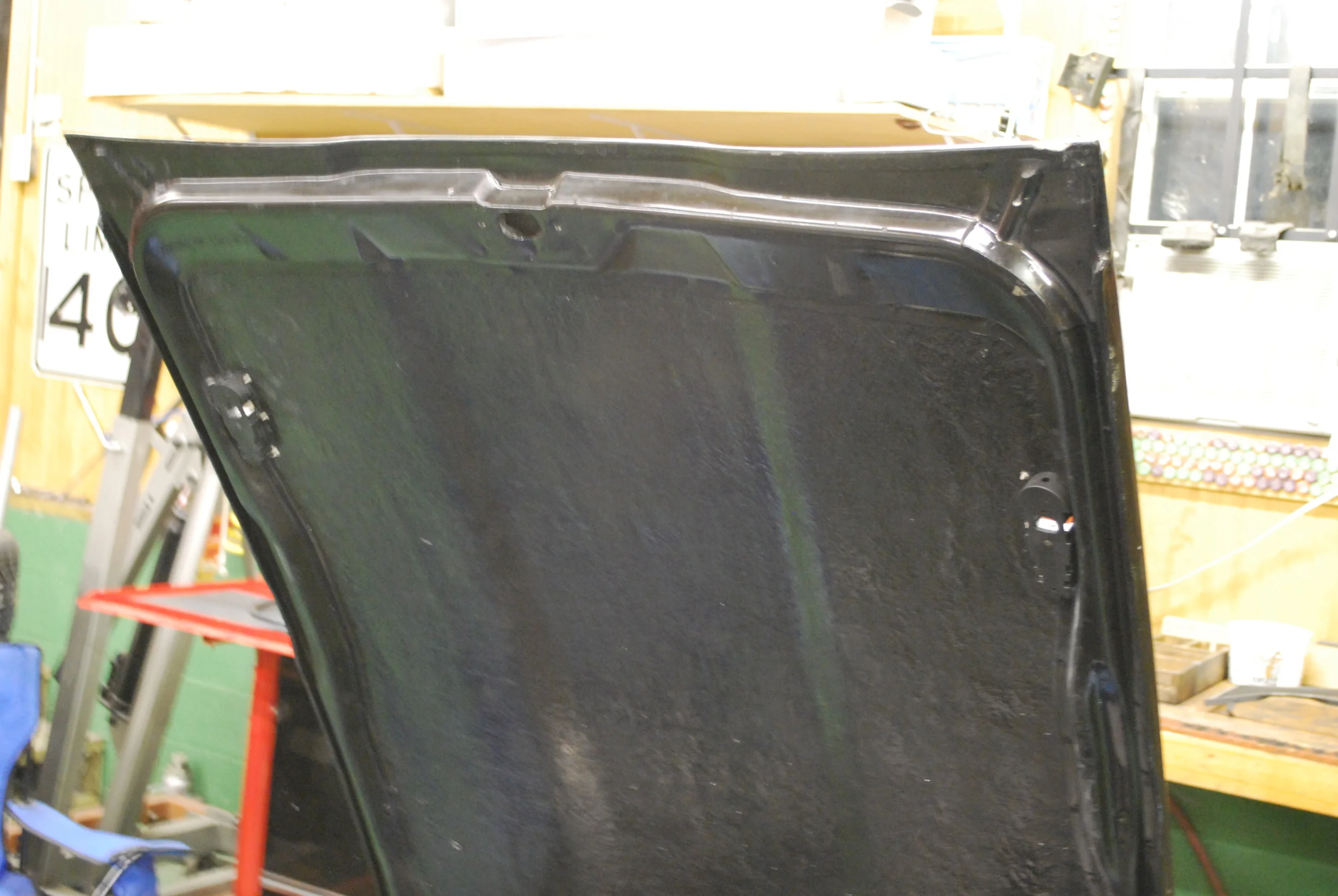
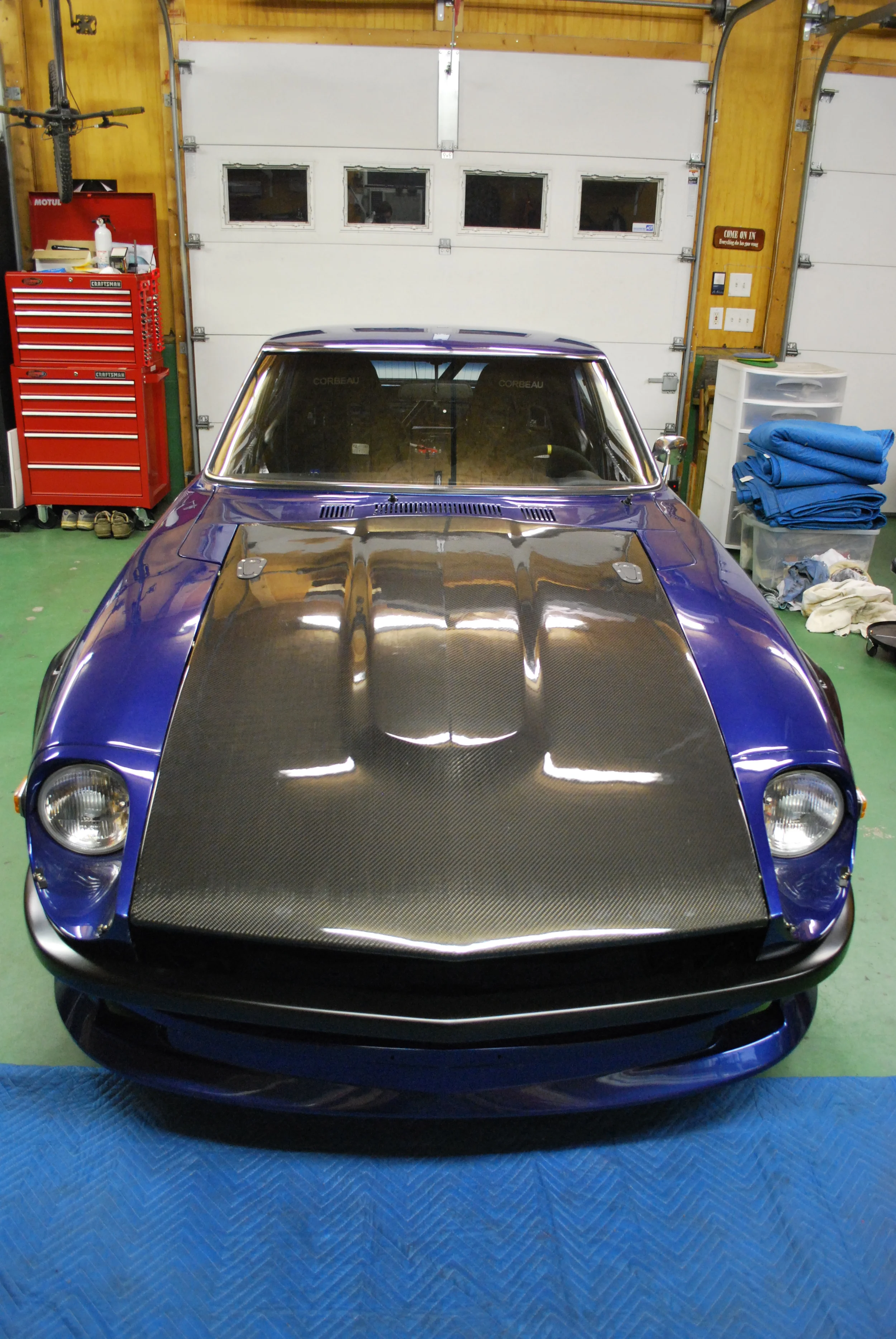
With the factory hood latch removed to clear the VQ intake I needed something to replace it with. I wanted something more finished looking then traditional hood pins and after seeing Aerocatch's flush mount 'hood pin' design I was sold. I am using a cheap carbon/fiberglass hood from RaceOnUSA. It replicates the factory hood with the inner frame and mounting points so this install should be similar for a standard steel hood, just a little more tedious to cut out.
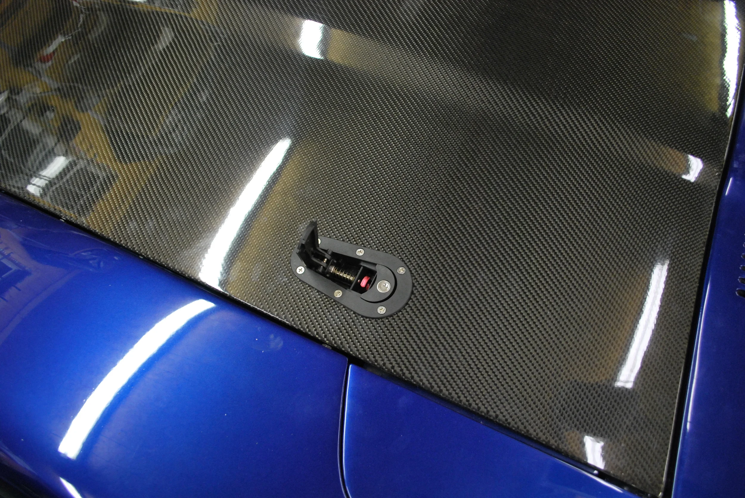
The Aerocatch hood pins are flush mounted on the hood and engage a traditional style hood pin that sits below flush. To install them the pin needs to be mounted to the chassis and the hood needs to be cutout for the Aerocatch receiver. After analyzing different mounting positions I decided the best place to mount the pins was on the fender supports right in front of the inspection lids. This allows for easy mounting of the hood pin without further cluttering the firewall and minimal trimming of the hood support frame,
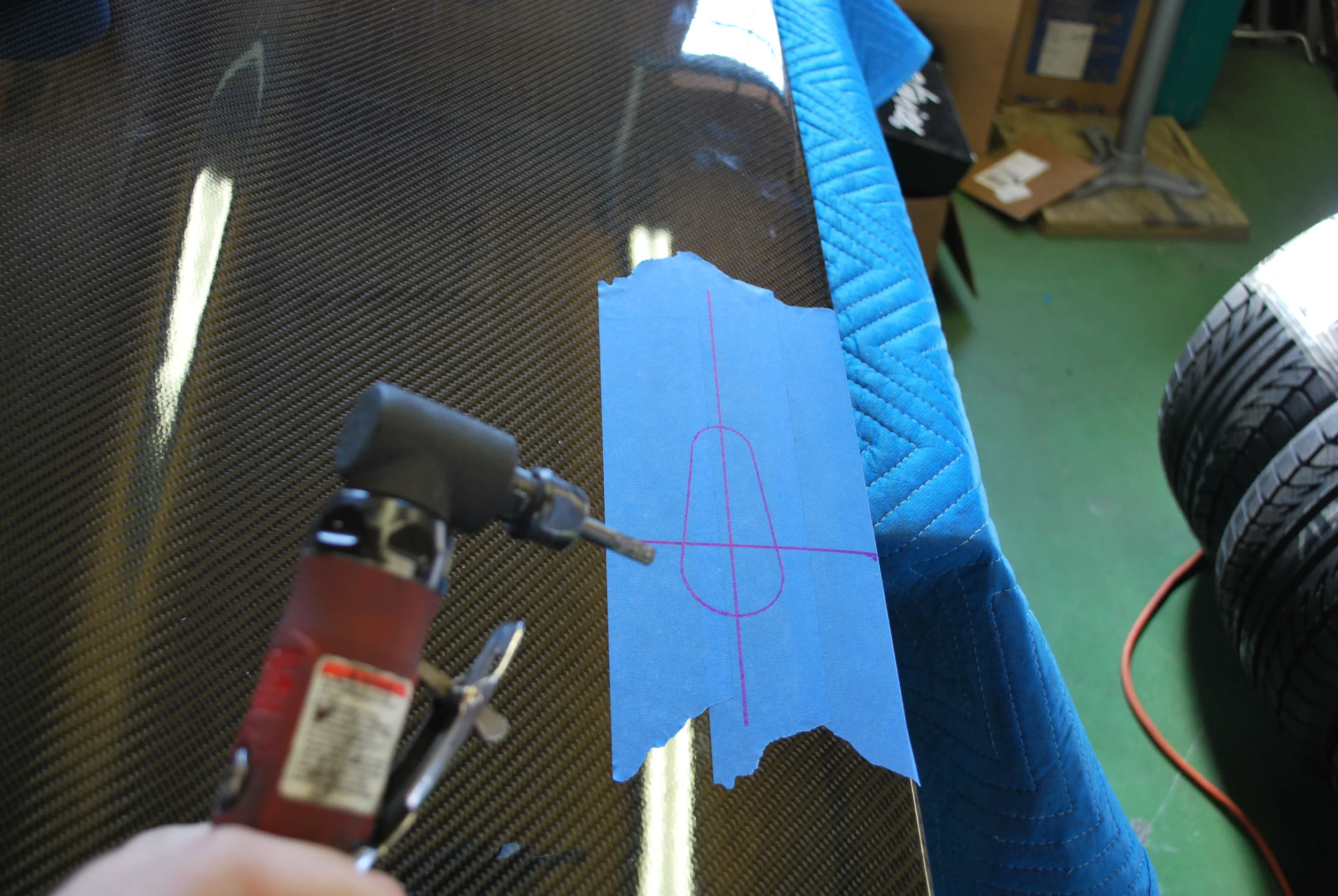
After measuring where they would be installed I laid out the location on the hood and traced the cut out with the patterns provided in the kit. I went in far enough so I would not cut into the frame of the hood
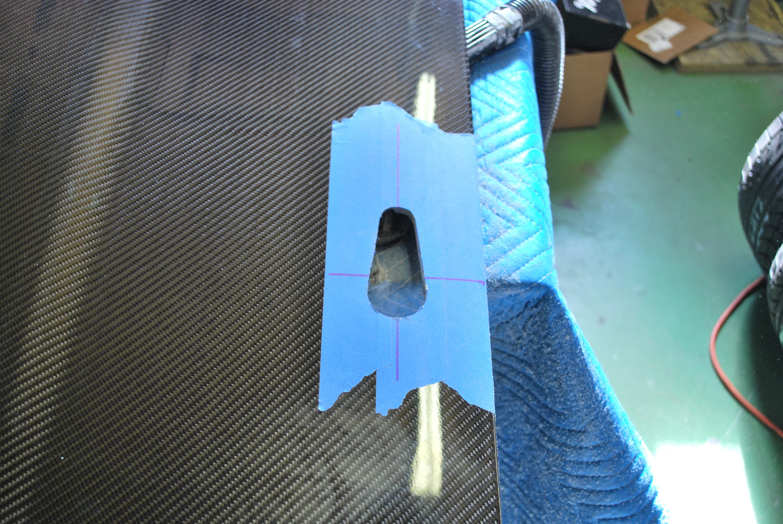
I started the cutout with hole saws and then used a carbide bit on a 90 degree die grinder to finish it. The receiver has very little overhang so care must be taken to get the hole as accurate as possible.
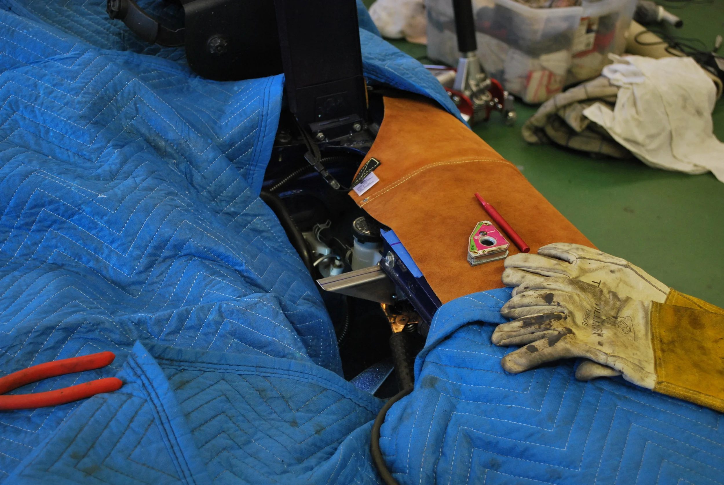
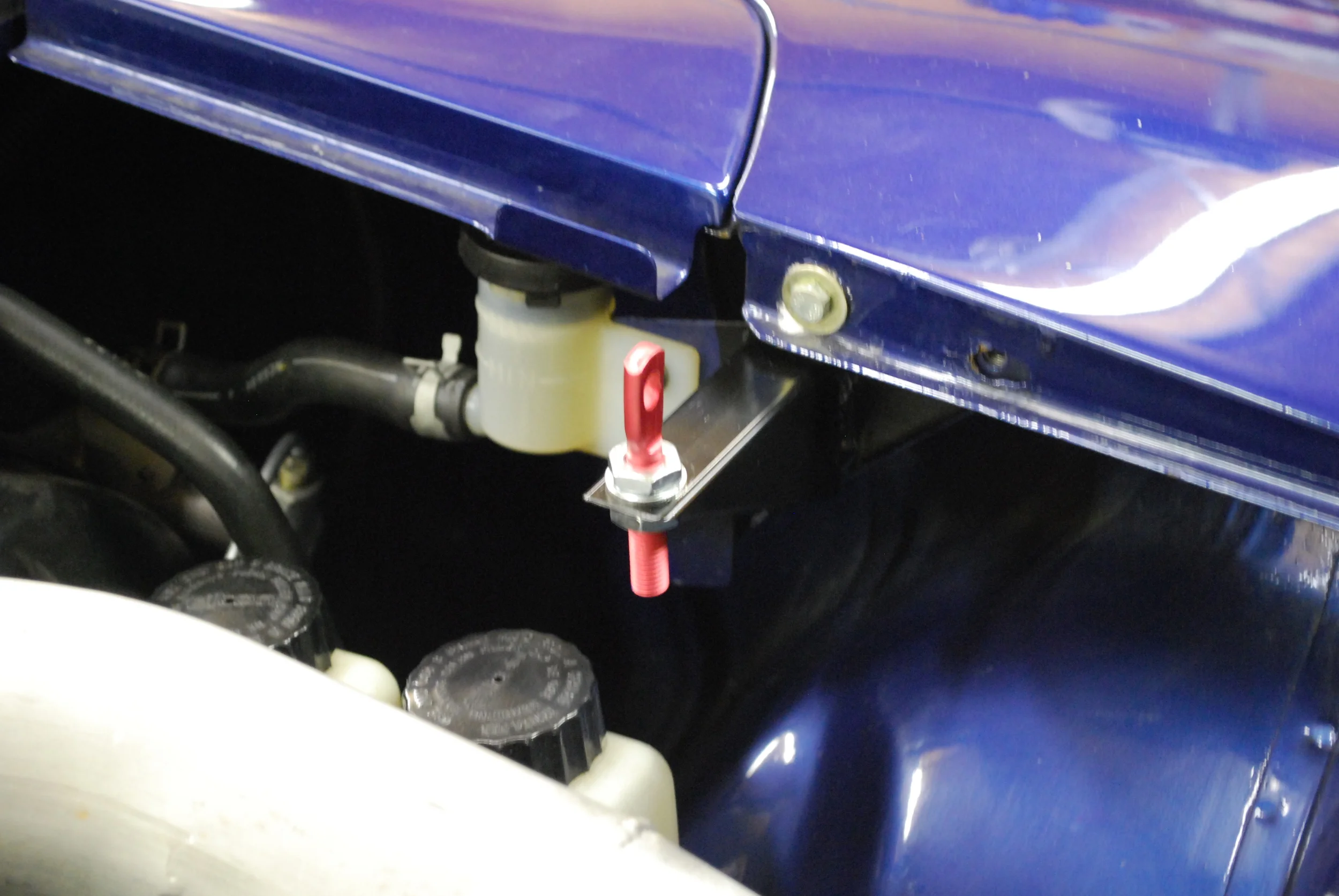
With the cutout made I carried the centerline out to the fender to aid in mounting bracket fabrication. Mounts were cut from a section of scrap 1.00" x 2.00" 0.060"W tubing. Once tacked in place and double checked with the hood shut they were welded in place.
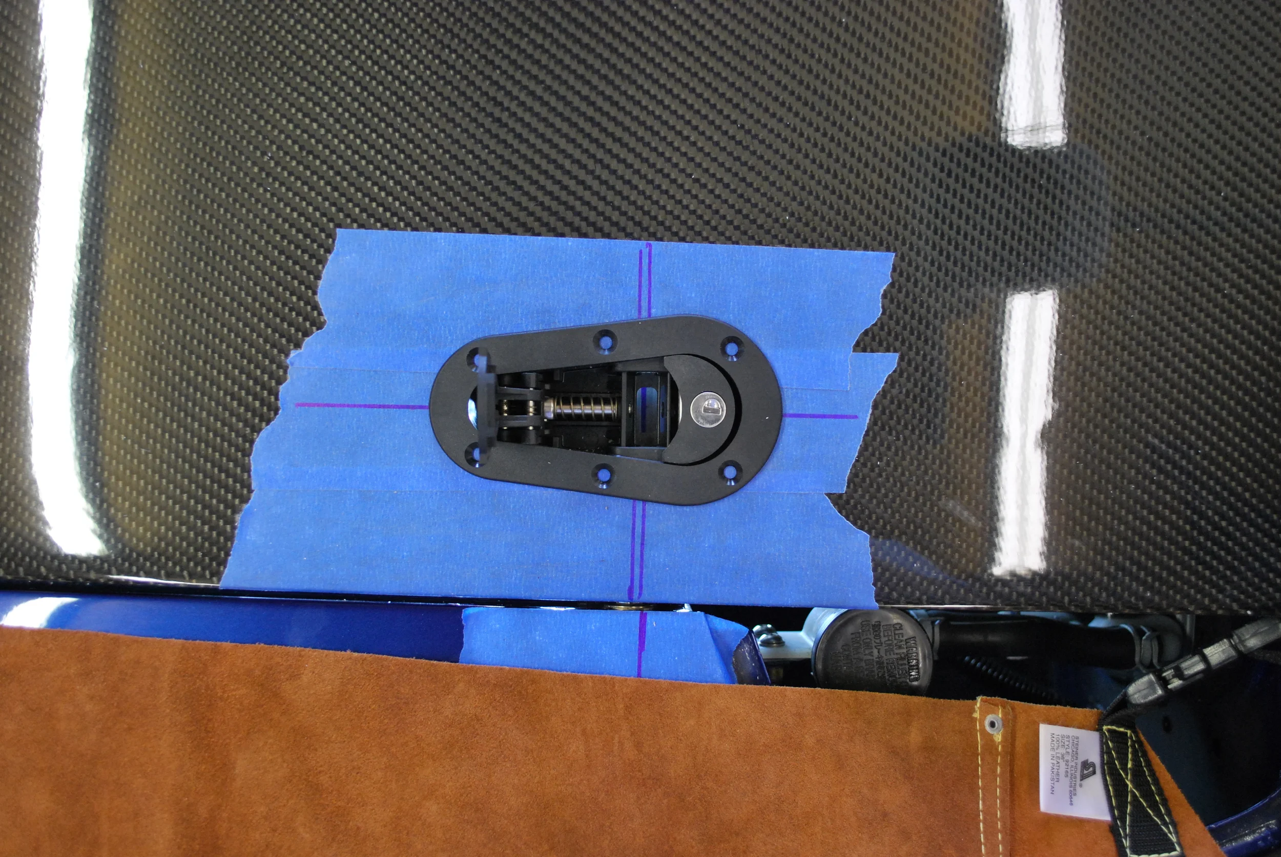
With the mounts welded and the hood in place a pilot hole was drilled for the pin. Below is the finish mount finish with a little paint.
With everything installed I tested the operation and found that the opening in the Aerocatch was not quite large enough to account for the angle change as the hood was raised. The opening was easily trimming a little larger everything operated smoothly.
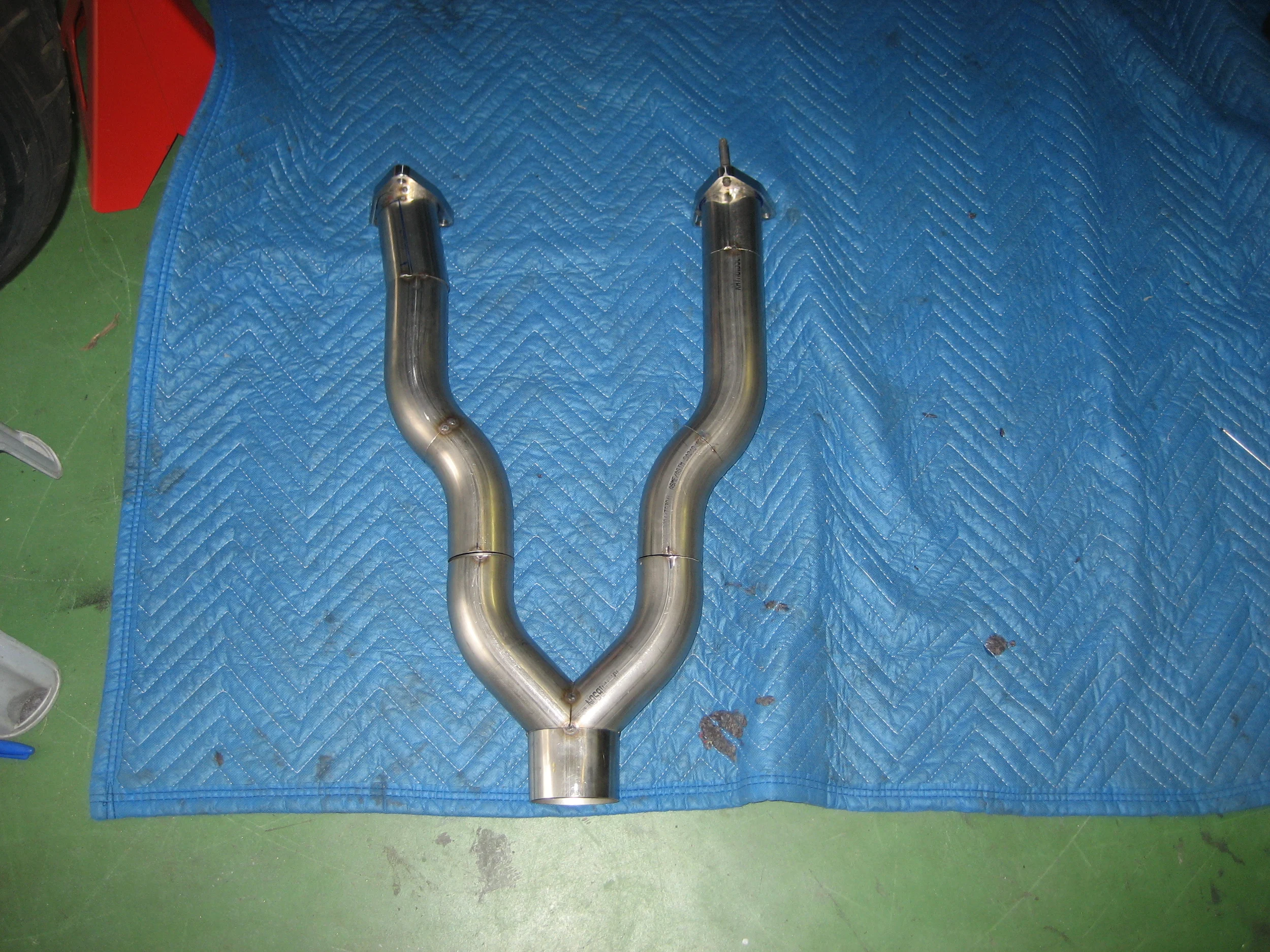
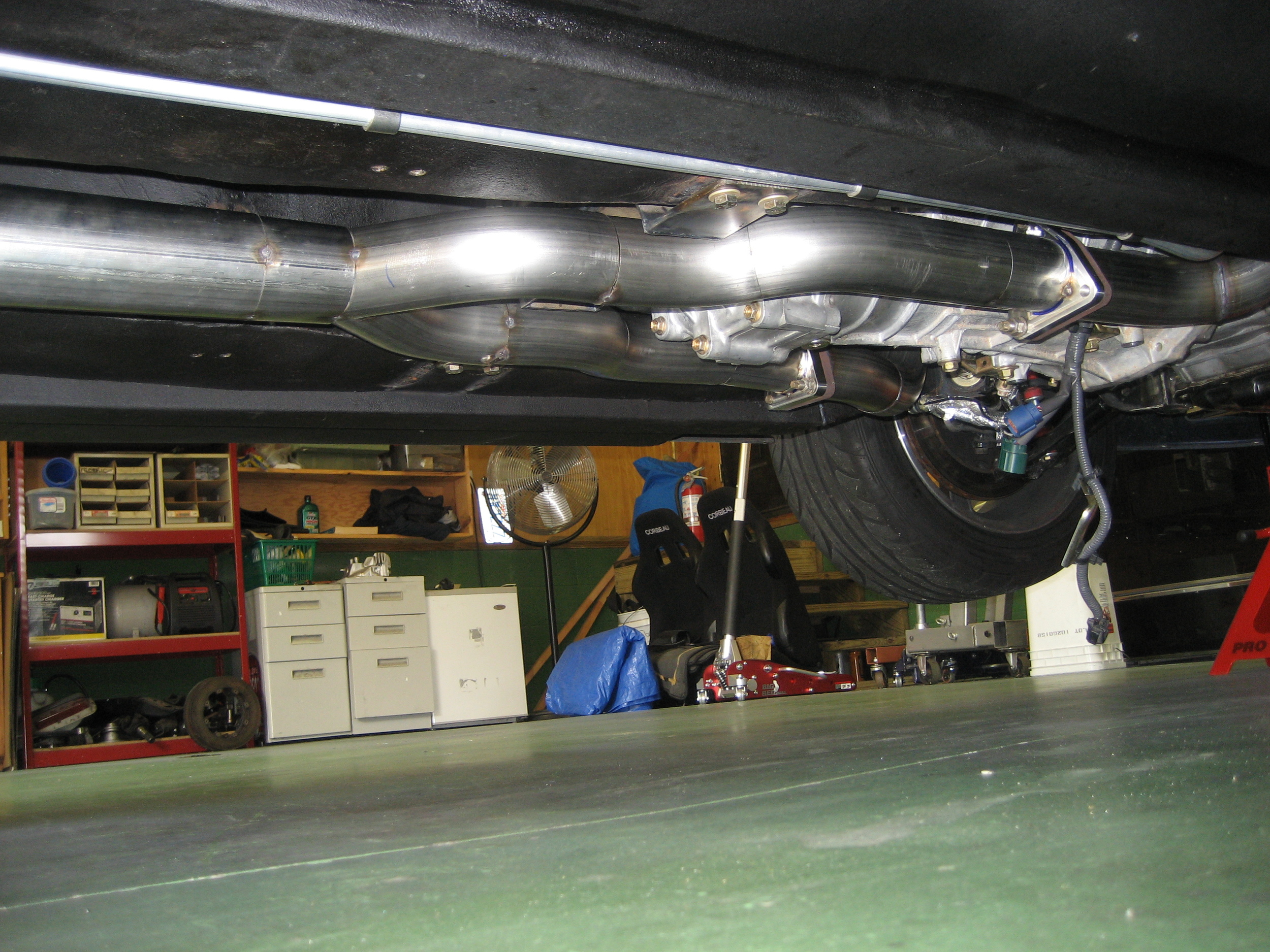
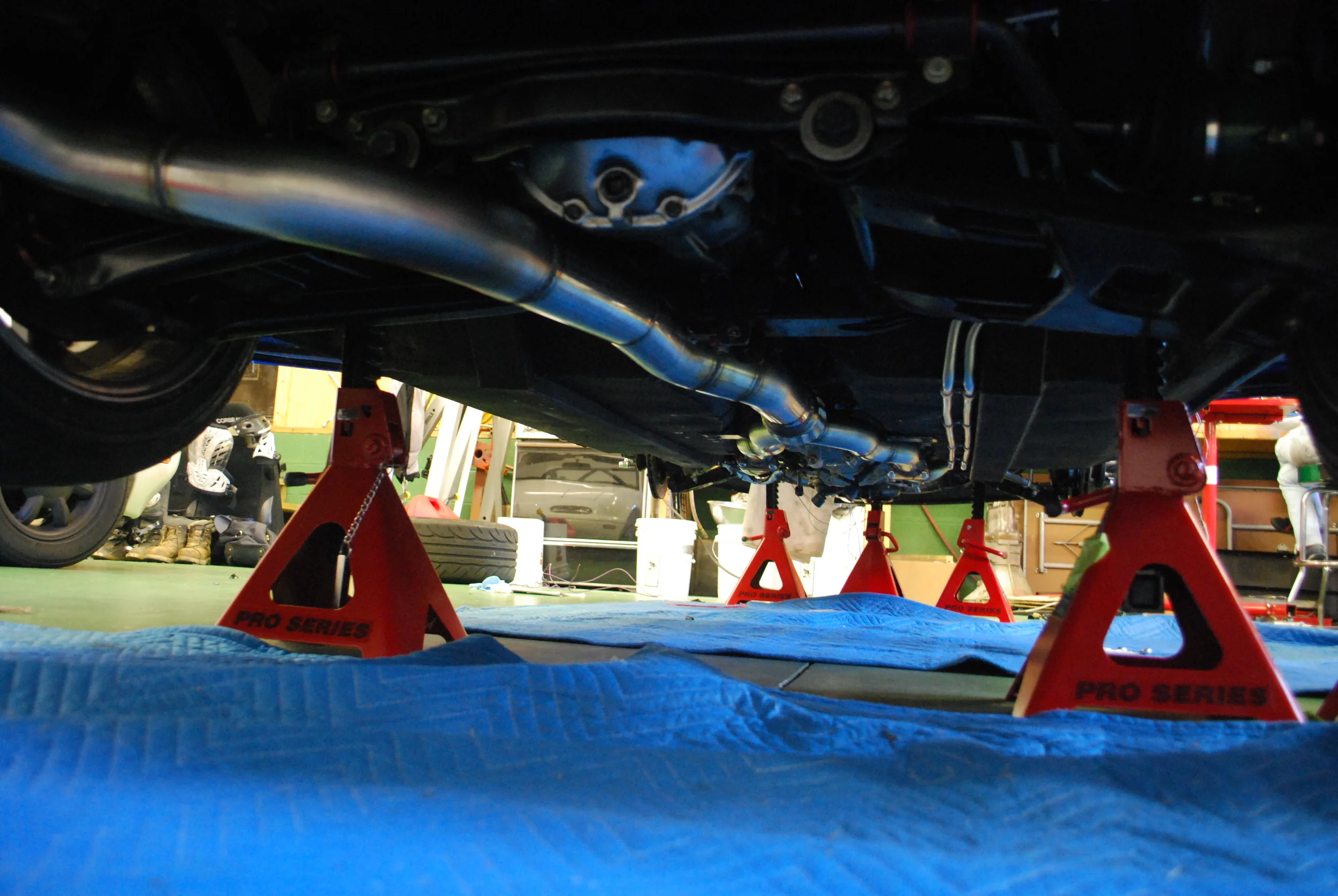
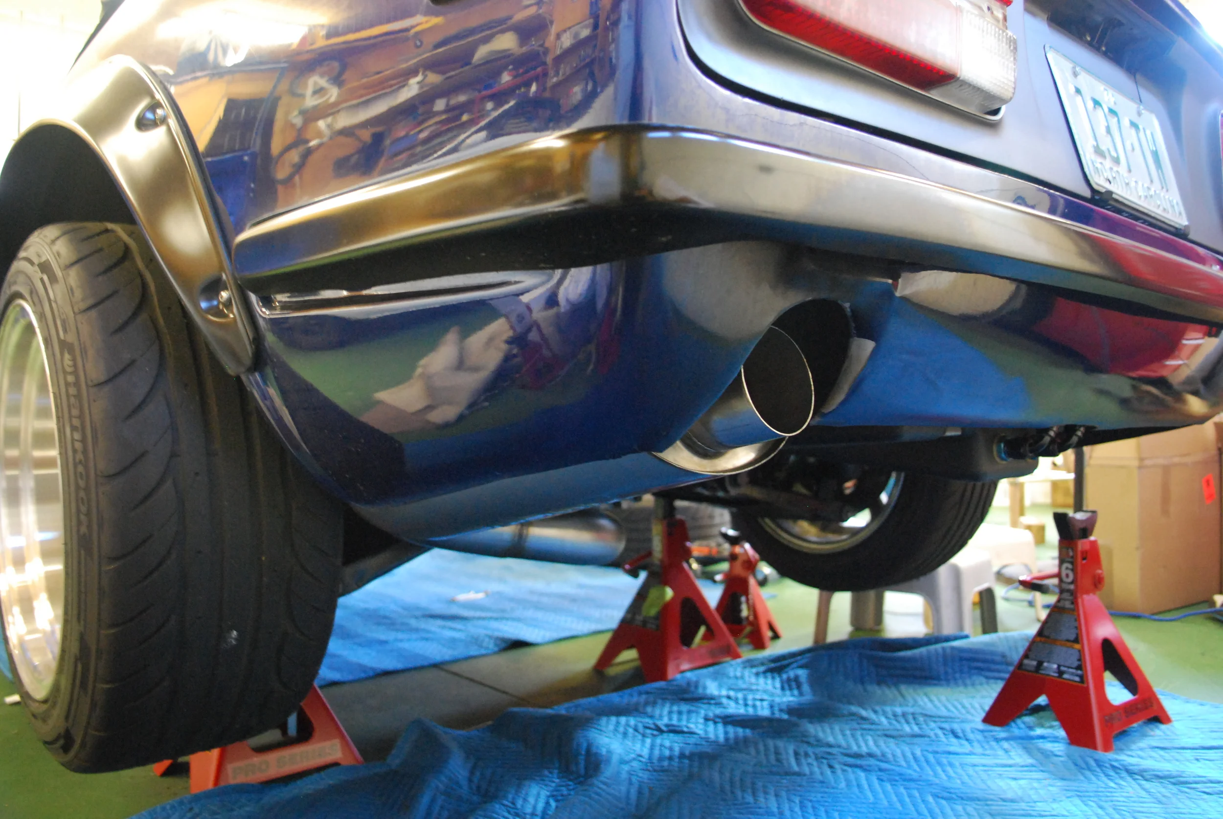
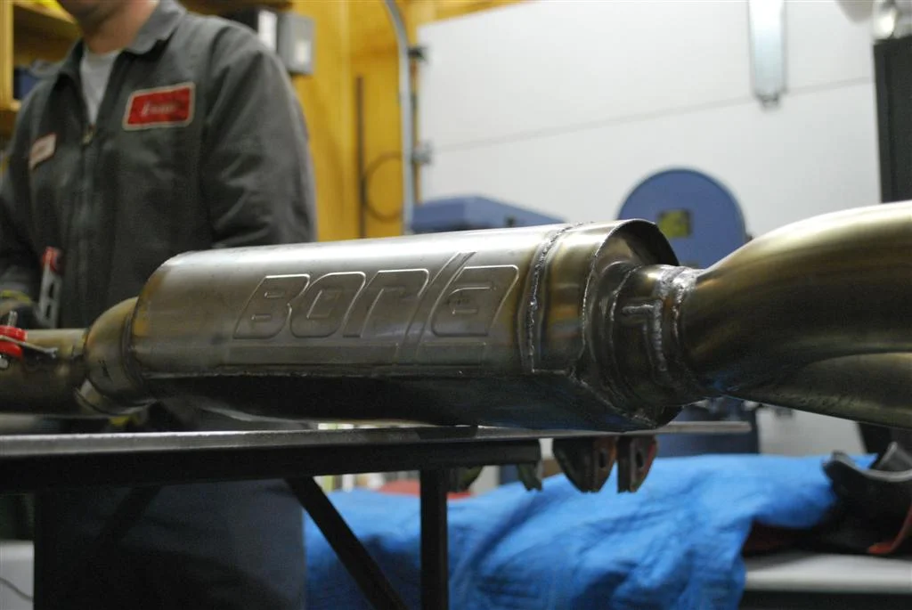
It took me a while to figure out what exactly I wanted to do with the exhaust. I ultimately decided to run dual 2.5" tubing off of the manifolds and join them behind the transmission to single 3" tubing. I decided on this route mainly due to the simplicity of routing and cost. The entire system is built from mandrel bent 16 Ga 304SS tubing and a XR-1 Oval Borla muffler in the rear. The initial installation sounded great at WOT but was extremely loud at cruise and had substantial drone, a second round muffler reworked into a 'D' shape was installed in the transmission tunnel which helped substantially. The system is still quite loud but is tolerable for cruising and longer trips.
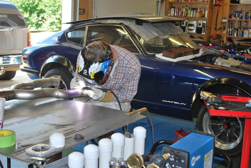
This was my first stainless steel project and there was a bit of a learning curve with the welding, but overall it out nice. If I was going to do it over again I would have picked up some Solar Flux for the inside of the welds, this would have made everything look much nicer. I picked up a few additional tools to complete this project....the main one being a Milwaukee Dry-Cut chop saw. If you plan on doing a lot of tubing this is a great tool to have. It cut the tubing easily without much of a mess and makes nice even cuts for welding. For this project I purchased all the tubing from Global Technology and Engineering, Ive found they have pretty good prices and you can buy the bends in 15 degree increments up to 90.
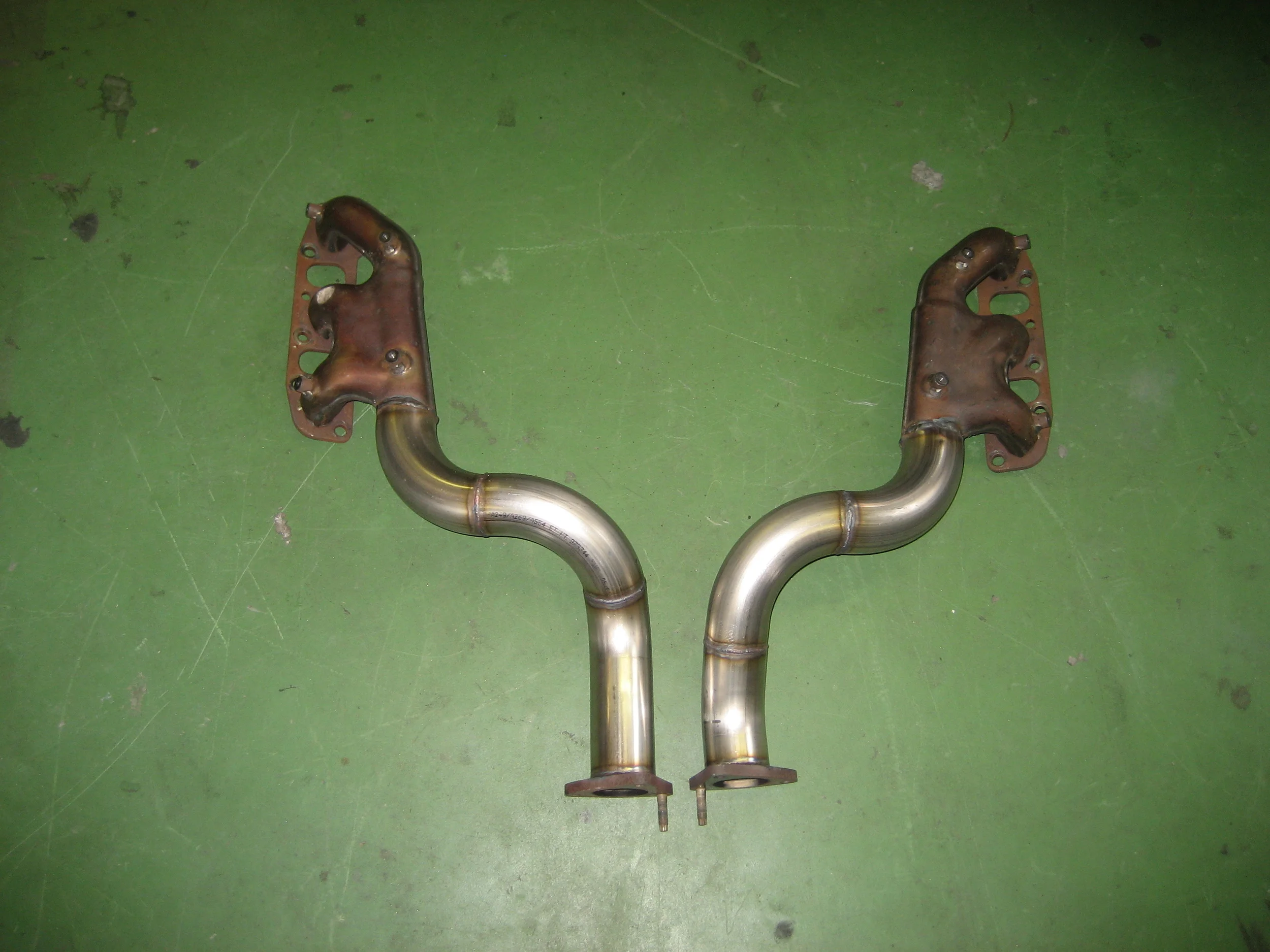
The 350z manifold outlets point straight out the rear, pointing directly at the firewall of the 240z. Since I eventually plan to go turbo and will fabricate headers at that point I wanted to save money where I could I decided to modify the factory manifolds for the initial N/A installation. I cut the ends of the OEM manifolds and welded tubing directly to them, turning the exhaust down the firewall ad into the transmission tunnel. I had some concern about durability of the weld, but it has held up very well without any cracking issues. I welded the joint with standard mild steel welding wire in my MIG.
To mount the exhaust to the manifolds I opted to use the factory flanges. I drew up mating flanges and had them CNC cut at work from 1/2" 304SS. It took a while to whittle them out but they turned out beautiful. Looking back I probably would have used V-Bands, but at the time the extra expense was not worth it to me. I've also had issues removing V-bands after they get fused in place over time.
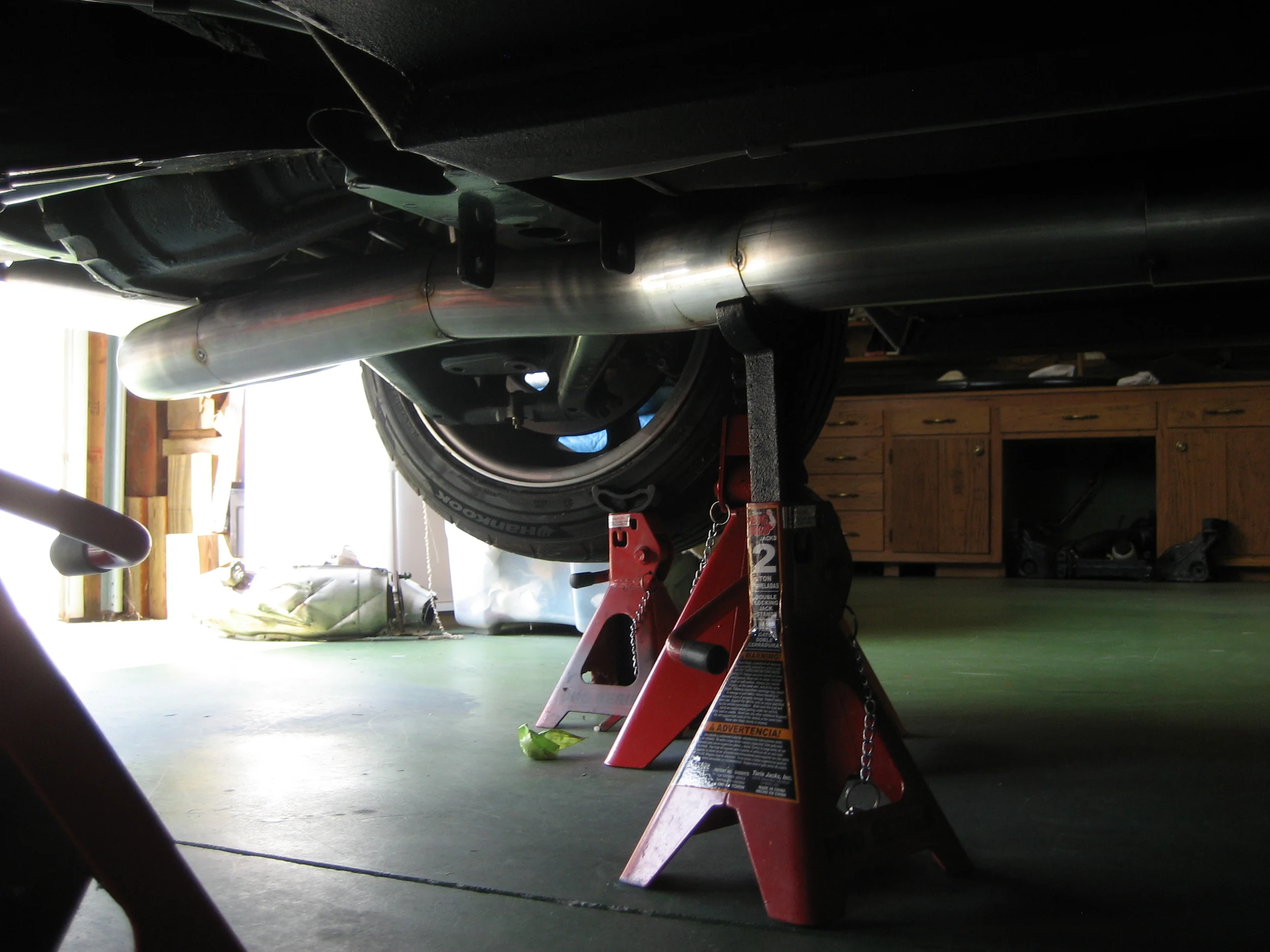
I was able to get the exhaust pretty tucked up under the car, it is even with my frame rails. The transmission crossmember also worked out well allowing for plenty of space to keep the exhaust tucked up. You can see the location of the flanges here as well, they will be easy to hook up to any exhaust header/turbo layout in the future
Welding and more welding...It took several hours to finish welding the exhaust. I added a flex pipe as well as 4 oxygen sensor bungs in the down pipes to finish it up.
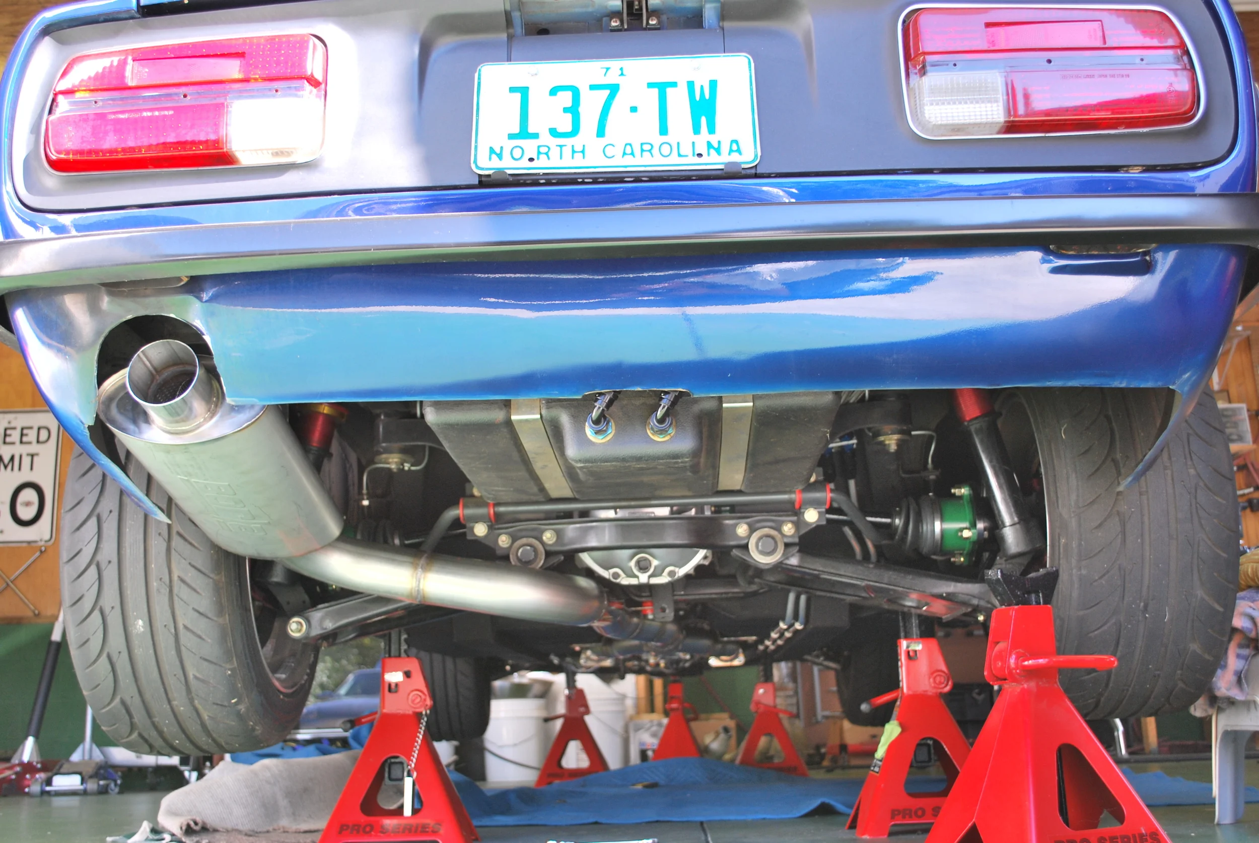
I used Summit Racing exhaust mounts to hang the rear of the exhaust, one at the muffler and one at the differential cross member. They are basically just strip of stainless with a nice snap together polyurethane bushing.... and are WAY over priced.
After getting the car on the road the first thing I realized was that my exhaust was way too loud for the street, however the worst part wasn't the noise but the drone. There was so much drone that for a trip of any distance I had to put in ear plugs. When I built the exhaust I knew I might have issues with drone but i was hoping for the best.....
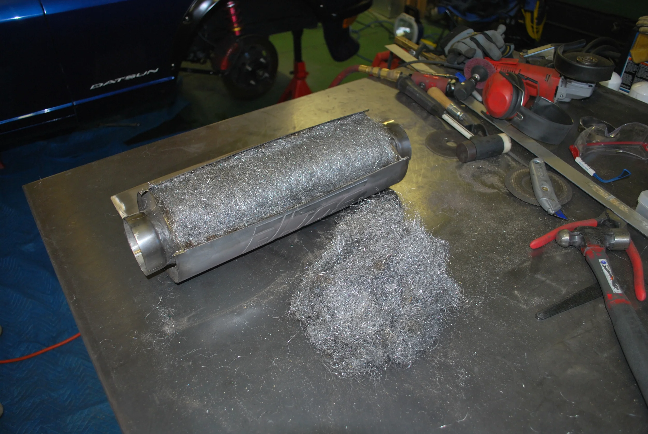
I talked with Borla tech support about the issue and they were very helpful. They told me the oval XR-1 was pretty much the same as their XS and turbo street muffler since it had a lot of packing. After looking at pictures of my car and the space limitation they recommended another XR-1 (round, 15" length) as a resonator as close to the engine as possible.
I the only place the muffler would fit was right behind the Y pipe in the transmission tunnel. Even at that location it required removing my flex joint and hacking up the muffler. I always wanted to know what these things looked like inside anyway....
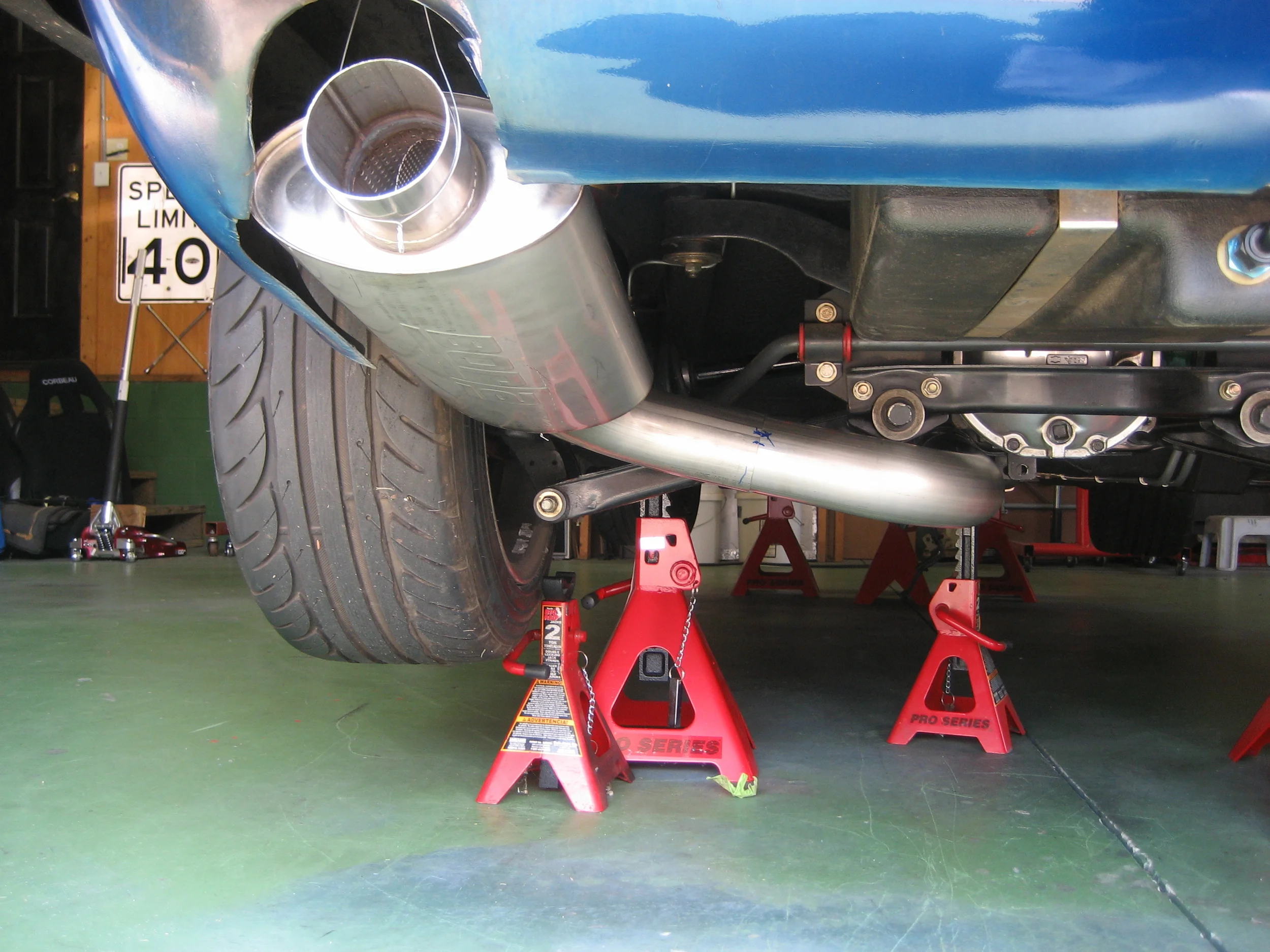
To gain much needed ground clearance I started by chopping the bottom of the muffler off and welding the section back on flat, this was a little tough to get straight but it turned out decent:
Finished product..you can see the horizontal section as well, this was a bit harder as the muffler didnt want to stay round after I cut it. I ended up taking about 1.5 inches out of the length. Still learning on the SS but it turned out pretty good.
Overall I very happy with the outcome, the car is MUCH quieter in partial throttle conditions and cruising around. Its still pretty angry sounding at WOT but you can hear the 'stock' VQ note hiding in here. Check out to videos page to hear how it sounds.
I decided to go with an aluminum Griffin Radiator that I sourced from Summit Racing. They have a wide selections of sizes with different outlet locations. The only thing I wasn't happy with was the poor welds. The radiator looks like it was MIG welded and then run back over in areas with a TIG. A friend purchased a similar unit from Jeg's and the welds on his were of much higher quality, all TIG welded. For the price though I cant complain, the radiator was right around 200 bucks and has performed flawlessly.
Since the radiator is universal fit all the mounting tabs and accessories have to be made. I started off by cutting out mounts from some scrap .06" Aluminum. When the radiator goes in permanently I will slot the mounting holes and mount it with rubber bushings to allow for flex and expansion.
Next up was the fan shroud which was made from 0.065 aluminum sheet. I trimmed the shroud to mount a 14" fan and installed riv-nuts for mounting, this would be a great application for nut plates on Rev 2. I chose to use a Flexilite S-Blade fan. I have had issues with cheaper electric fans before but this one has proven to be a good value. SPAL fans are always a top choice for me if there is room in the budget!
Punch flairs were added along to the top for a little style (Thanks to my Buddy Zach for lending me the die! http://www.prismmotorcycleco.com/). I used a Jeg's radiator overflow bottle, I was happy with the quality and how nice the 'rail' style mount was. I have the unit plumbed to recirculate, but the tank came with a petcock valve to install as an overflow if desired.
I connected the radiator using aluminum tubing an silicone connectors. A hump connector prevents issues with the engine vibration and movement.
The stock 350z fuel system is a dead-head style setup. This means there is a single supply line from the tank to the fuel rails. The fuel pressure is regulated at the tank. While fine for stock applications this is an area that needs some improvement when mods are made, especially in boosted applications.
The factory rails were converted to work with a fuel return, and were plumbed in parallel instead of series. This setup allows for more fuel that is cooler and well regulated.
To do this the factory damper flanges and connector tube were cut off. Then the ends of the rails were drilled out to match the ID of the main fuel rail tube. To finish the rails and allow easy hookup to AN fittings and braided tubing steel -6AN male fittings were welded to the ends of the rails. These are available from Summit Racing for a couple bucks each.
Factory damper flange cut off:
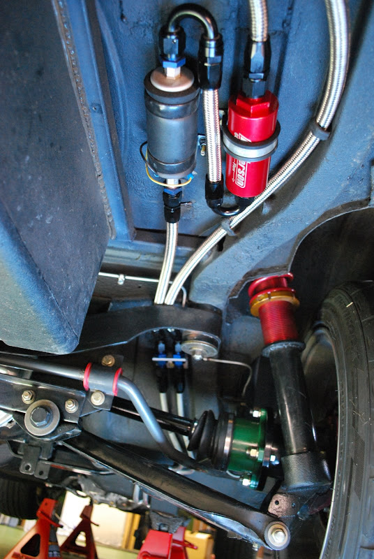
I'm using an adjustable Aeromotive fuel pressure regulator as well as a small in-line gauge to make adjustments easy from the engine bay. Note the ProFlow 350 Hose, its nylon braided hose that it super flexible and light. I prefer it in the engine bay over SS hose which is stiff and abrasive.
As I mentioned earlier, the rails are plumbed in parallel and are fed by a -8AN line that splits into two -6AN lines. Each rail dumps to a side port on the regulator which in turn dumps to a -8AN return line that flows back to the tank.
Originally when I had the L28 in the car I ran two stainless braided lines from the tank to the fuel rails. It worked but i didn't really like the setup because it didn't allow for much flexibility. If anything needed to be changed or rearranged everything would need to be re-plumbed.
I decided to run hard line this time around. I am using 1/2" aluminum hard line that is terminated at the ends with bulkhead fittings on a bracket. I'm using stainless braided line in the back under the car and proflow nylon braided under the hood.
I kept my original fuel setup from the L28 which includes a Walboro 255 inline pump, Peterson fuel filter, and a Jazz fuel cell. In the future I would like to swap back to the factory tank setup and install an in-tank pump.
I used stamped stainless clamps and riv-nuts to hold the lines in place, they are made by Kugel Komponents (http://www.kugelkomponents.com/).
After tackling the shifter location the rest of the driver controls were next.
One of the things that always frustrated me with my L28et setup was the clutch. With different performance clutches I was using it was very difficult to get the feel right. I experimented with different master cylinders and ultimately to get the throw how I wanted, engagement took a significant amount of force. Enough to distort the firewall and require MC bracing. The purpose of installing the VQ was to build a street machine first and a track car second, I wanted to the clutch to be comfortable but still have a good feel. Having driven a 350z I knew the clutch had a nice feel so I decided to see if the factory 350z MC could be incorporated. With a quick mock-up and a few measurement it looked feasible.
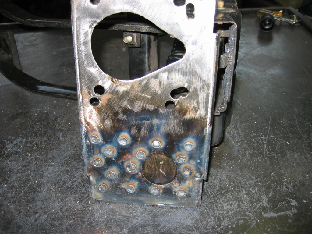
The mounting pattern was a bit wider then the 240z master cylinder so I started by trimming the corners of the pedal box and folding the edge down. To regain some of the strength lost by the removing the flange and to help reinforce the box for stiffer setups down the road I welded 0.125" plate over the area.
After a little cleanup and drilling for the new MC pattern the finished result is below.
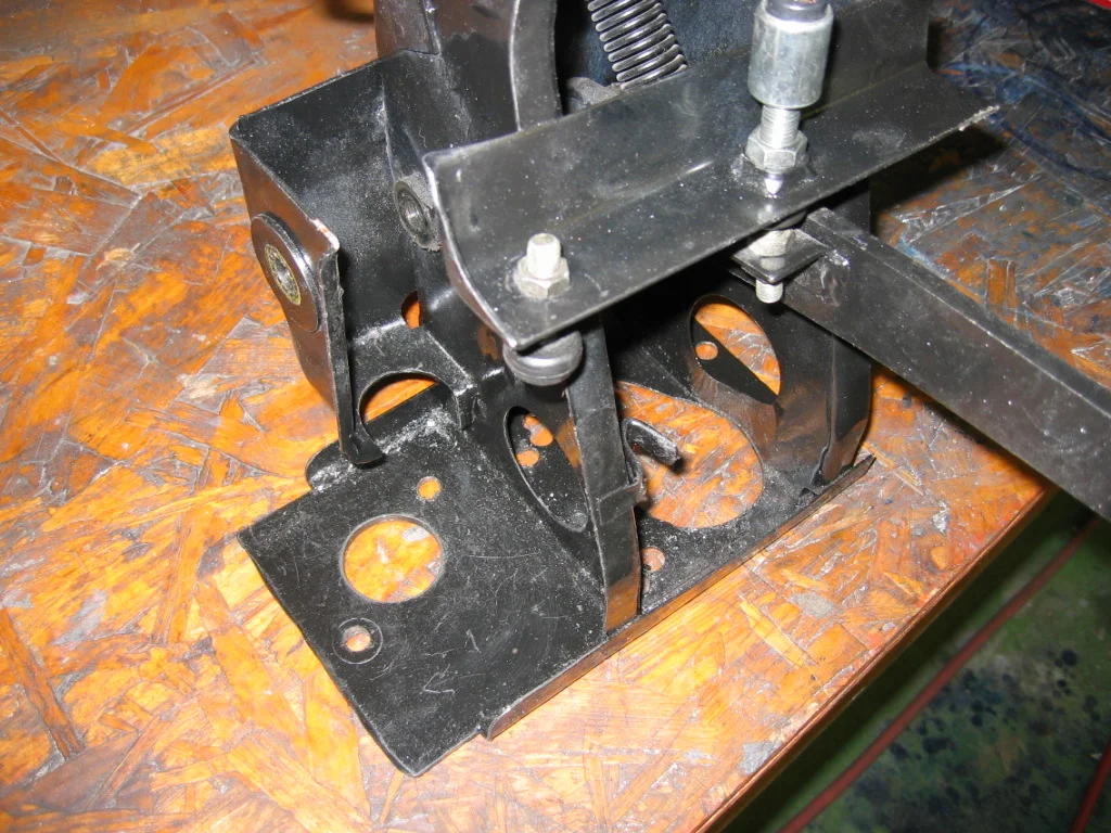
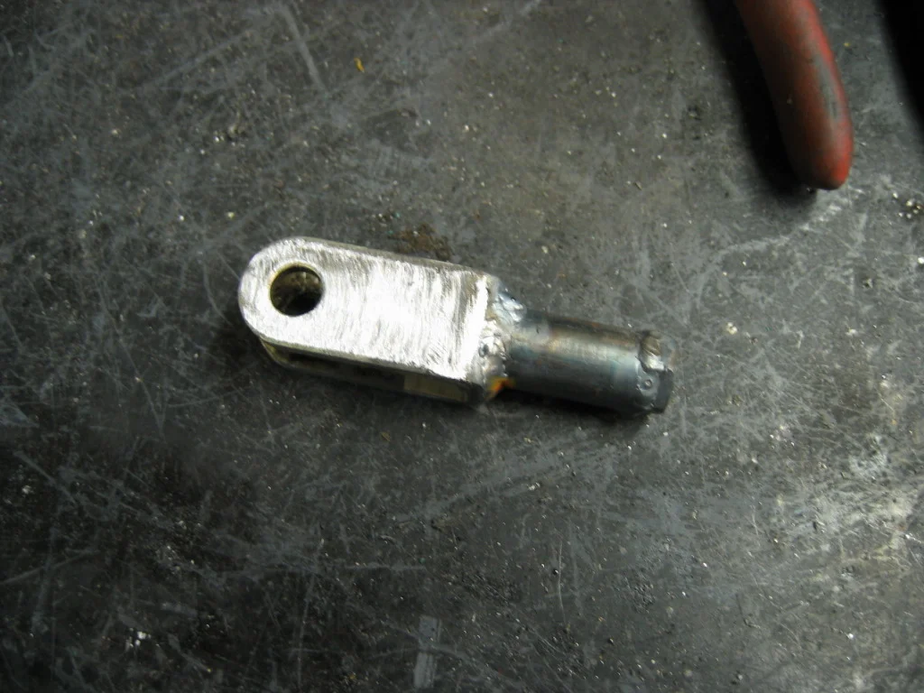
The pushrods and clevis assembly were shorter on the 350z unit compared to that of the 240z. The clevis was extended using a piece of tubing and a nut so that the pedal height and adjustment were correct. Its not the most elegant but it works well.
Installation was tight with the larger 280z brake booster, however everything clears. The lip on the firewall reinforcement had to be trimmed down for the wider bolt pattern of the 350z unit.
The final installation and plumbing is shown below. I mounted the 350z reservoir to using a couple rivnuts. I plumbed the unit directly to the 350z slave without a delay valve. Overall I am very happy with the results, the clutch works well and feels great.
Next was mounting the 350z drive by wire pedal. Keeping the factory ECU meant that I could use the DBW throttle body and pedal. The feel is great and it makes for a clean installation. The pedal was almost a direct replacement! I made a new mounting plate to match the DBW pedal pattern and welded it to the factory mount. After fitment I installed a new pedal stop at the bottom as well.